Doc:2.6/Tutorials/Modeling/Curves/Bézier
Working example
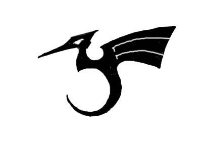
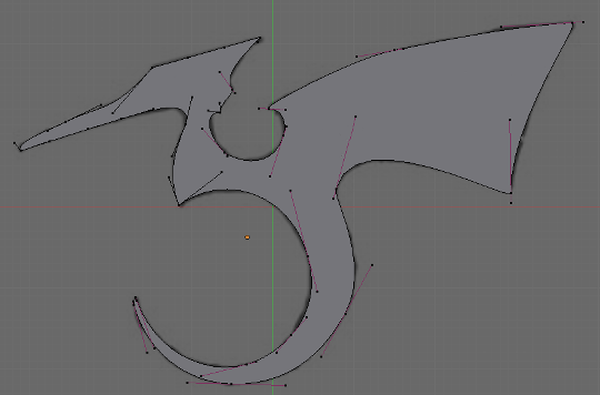
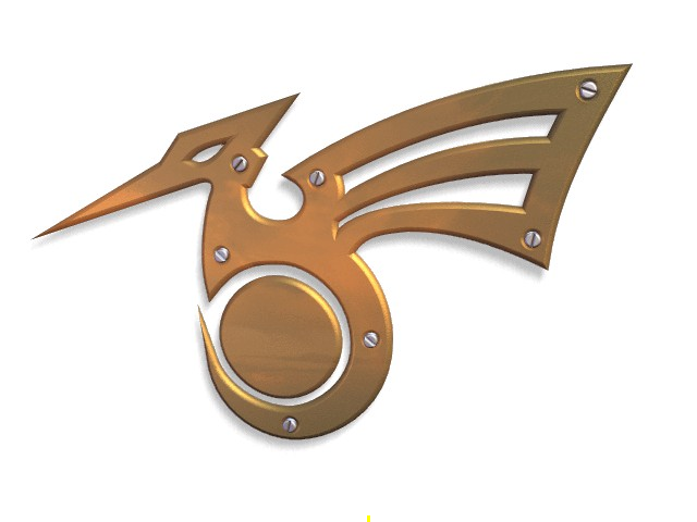
Blender's curve tools provide a quick and easy way to build great looking extruded text and logos. We will use these tools to turn a rough sketch of a logo into a finished 3D object. The sketched logo shows the design of the logo we will be building.
First, we will import our original sketch so that we can use it as a template. To load the image:
- Press N to toggle the View Properties Panel
- Click the Background Images checkbox to enable background images.
- Click Add image
- Click Open
- Navigate to our image and select it with LMB
 and then click Open Image in the top right hand corner.
 - You can change the strength of the image by altering the Opacity slider
Read more about background images »
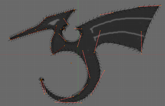
Add a new curve by pressing ⇧ ShiftA and then navigating to Add Object Menu » Add Curve » Bezier. A curved segment will appear. We will move and add points to make a closed shape that describes the logo you are trying to trace.
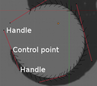
You can add points to the curve by selecting one of the two control points, then holding Ctrl and clicking LMB ![]() (or by pressing E to extrude). Note that the new point will be connected to the previously selected point. Once a point has been added, it can be moved by selecting the control point and pressing G. You can change the angle of the curve by grabbing and moving the handles associated with each point.
(or by pressing E to extrude). Note that the new point will be connected to the previously selected point. Once a point has been added, it can be moved by selecting the control point and pressing G. You can change the angle of the curve by grabbing and moving the handles associated with each point.
You can also add a new point between two existing points by selecting the two points and pressing W » subdivide. Points can be removed by selecting them and pressing X » Select. To cut a curve in two, select two adjacent control vertices and press X » Segment.
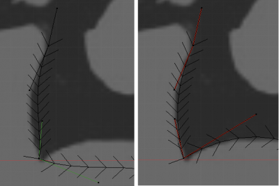
To make sharp corners, select a control vertex and press VV to convert the handle type to Vector. You will notice that the color of the handles changes to green. These will change to Free handles once they are moved.
Read more about Handle Types »
To close the curve and turn it into a single continuous loop, select the two endpoints of your curve and press F to make a segment. You may need to manipulate additional handles to get the shape you want.
At the moment, the curve is closed but but not solid. To make it solid, switch the curve shape from 3D to 2D. Press Z to enter shaded mode and see the curve as a solid shape. We now want to cut some holes into this shape to show the eyes and wing details of the dragon.
When working with curves, Blender automatically detects holes in the surface and handles them according to the following rules:
- A closed curve is always considered the boundary of a surface and hence rendered as a flat surface.
- If a closed curve is completely included within another one, the inner one is subtracted from the outer one, effectively defining a hole.
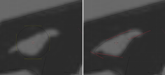
Return to wireframe mode with Z and add a Bezier circle with Add Curve » Circle. Scale the circle down to an appropriate size with S and move it with G. Shape the circle using the techniques we have learned. Remember to add control points to the circle if you need them with W » Subdivide
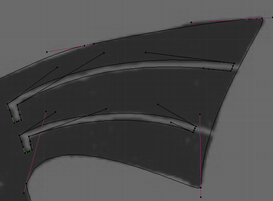
Create a wing cutout by adding a Bézier circle, converting the necessary the points to sharp corners (vector handles), and then adjusting as necessary. You can duplicate this outline to save time when creating the second wing cutout. Select all the control points of the wing cutout, duplicate the selection with ⇧ ShiftD and move the new points into position.
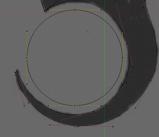
To add more geometry that is not connected to the main body (placing an orb in the dragon's curved tail for example), use the ⇧ ShiftA menu to add more curves as shown below.
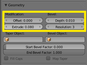
Now that we have the curve, we need to set its thickness and beveling options. With the curve selected, go to the Geometry panel of the Curves editor window. The Extrude parameter sets the thickness of the extrusion while depth sets the size of the bevel. Resolutions determines how sharp or curved the bevel will be.
When your logo model is complete, you can add materials and lights and make a nice rendering.
Read more about materials »
Read more about lighting »
To perform more complex modelling operations, convert the curve to a mesh with AltC >> Mesh. Note that this is a one-way operation: you cannot convert a mesh back into a curve.
