Doc:2.6/Manual/Physics/Soft Body/Combination With Armatures
Combination Soft Body with Armatures
You can use goals to either pin certain parts of a mesh to a location, or restrict the amount of movement away from the defined goal. So you may for example use armatures to animate your object but use a Goal group to define areas that are flexible and that react to Soft Body deformation. Since a simulation can be set up to take into account mass and gravity, you can easily create animated objects with realistic physical behavior using the Soft Body solver.
You can also use one of the following methods to combine Soft Bodies, objects and armatures:
- Soft Body vertices can be made the vertex parent of an empty, this empty can be the target of an IK solver.
- Using Bone stretching you can allow a bone to follow the length change of a Soft Body.
- You can use constraints to copy animated parameters of a bone onto an object.
- You can use a hook to bind a Soft Body to an armature driven object.
Swing example
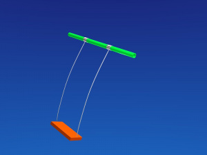
The Soft Body simulation will drive the free end of a pendulum. This movement is used to drive the seat of a swing. You could also use a similar simulation for a Bungee cord, if you make the cord less stiff.
- Add a plane. Rename this object to “
Pendulum”. - Change to Edit mode.
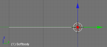
- Make sure you are in top view and delete the left half of the plane, so that all that remains are two vertices connected by an edge.
- Select one vertex and make it the sole member of a vertex group (weight 1). This vertex will stay put. It is the “upper” vertex.
- Bring the “upper” vertex and the object center together, either by moving the vertices or the center.
- Tab out of Edit mode and enable Soft Body in Physics context for the object.
- Go to Soft Body Goal panel and select in Vertex Group field the vertex group of the “upper” vertex.
- Set under Goal Settings: Stiffness value to 0.
This creates a rig where the “upper” vertex is pinned, but the other vertex (and therefore the edge) is fully affected by the simulation.
When you scrub or play (AltA) your animation, the vertex associated with a goal stays put, but the other is free to be affected by the physics simulation. Since the edge is pretty stiff, and there is gravity and mass and thus inertia, the vertex at the other end swings back and forth, and will eventually come to a stop, even if you turn off all damping. If you don’t want it to stop, you could either increase the calculation accuracy, or use the Error Limit paremeter in Soft Body Solver panel, which is designed specifically for these types of simulations.
The free vertex will become the IK target for an armature. Therefore we need to create a second vertex group.
- Change to Edit mode.
- Select the “lower” vertex.
- Press CtrlG → Assign to New Group and rename the vertex group “
TargetGroup”. - Change back to Object mode.
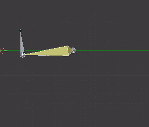
- Insert an Armature with a single bone.
- Ensure that the armature is selected and change to Edit mode.
- Move the tip of the bone to the “lower” vertex.
- Change to Pose mode and ensure that the bone is selected.
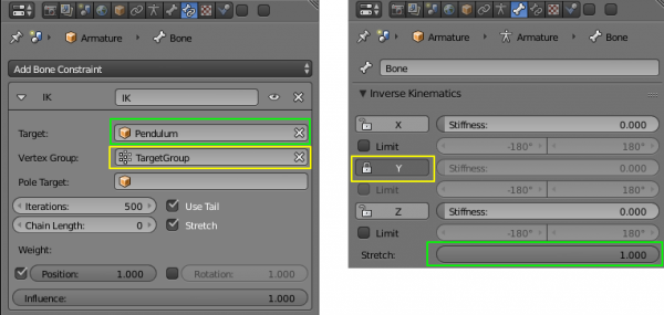
- Add an Inverse Kinematics constraint to the bone (Bone Constraints panel, Add Constraint), use the object “
Pendulum” and the vertex group “TargetGroup” as target. - Set Stretch in the Inverse Kinematics panel of the Bone context to 1.0.
- Click on lock Y button in the Inverse Kinematics panel of the Bone context, so the bone doesn’t rotate around itself.
If you now play the animation, the bone swings back and forth. When the length of the object changes, the length of the bone also changes.
- Now extrude a second bone at an angle perpendicular to the first.
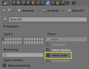
- Turn off Inherit Scale in the Relations panel of the Bone context, so that the second bone isn’t scaled when the the first bone is.
Then you can:
- add objects for the swing crossbeam, cord and seat of the swing;
- place swing crossbeam to the "upper" vertex;
- place swing cord to the armature first bone and parent to the first bone with CrlP > Set Parent To > Bone Relative;
- dublicate swing cord, pendulum and armature for second cord and place the dublicated second swing respectively;
- place the seat object to the armature second bone;
- parent the seat of the swing to this second bone.
Animation rezult is here.
