「Doc:2.6/Manual/Modeling/Meshes/Editing/Deforming」の版間の差分
(→Example: grammar) |
細 (1版 をインポートしました) |
(相違点なし)
| |
2018年6月29日 (金) 04:50時点における最新版
Page status (reviewing guidelines)
Text
move?
|
Deforming Geometry
Push/Pull
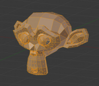
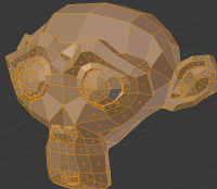
Similar to shrink/flatten, this transformation consists of translating all selected elements along the line joining their original position to the Average position of the points. All translations are of same value, and are controlled by the mouse. It results in something that looks a bit like the scale effect, but much more deforming.
Note that unlike the preceding ones, you can lock this transformation on axis – even though this has no real interest (except perhaps with a “plane locking”…).
Warp
Mode: Edit mode
Hotkey: ⇧ ShiftW
Menu: Mesh/Curve/Surface » Transform » Warp
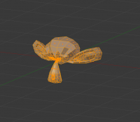
The Warp transformation is useful in very specific cases. It works by warping the selected elements around the 3D cursor (always the 3D cursor; it does not take into account the pivot point setting…). It is also view-dependent. The points that line up vertically with the cursor will remain in place. Each point's distance to the cursor's horizontal position corresponds to the radius it will be from the cursor after the tool has been activated. The tool will then wrap the point around the cursor. A value of 360 will wrap the mesh into a complete circle, so that the points furthest to the left and the right will line up with each other and the cursor position.
To use this tool, set the cursor in the view where the center should be. Activate the tool, then move the cursor or enter the value of the angle the mesh should be warped to.
Example
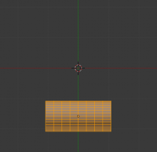
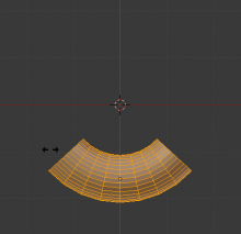
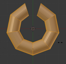
A cylinder is warped into a semicircular shape
- Switch to top view and move the mesh away from the 3D cursor. This distance defines the radius of the warp.
- Place the mesh in Edit mode (⇆ Tab) and press A to select all vertices. Press ⇧ ShiftW to activate the warp transform tool. Move the mouse left or right to interactively define the amount of warp.
Shear
Mode: Edit mode
Hotkey: CtrlAlt⇧ ShiftS
Menu: Object/Mesh/Curve/Surface » Transform » Shear
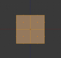
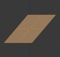
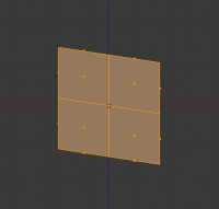
The Shear transformation applies a shearing on your selection of elements (in Edit mode, vertices/edges/control points/…). Like the other transform tools, it uses the view space, and is centered on the pivot point: the shear occurs along the view’s x-axis passing through the pivot point. Everything that is “above” this axis (i.e. has a positive y-axis position) will move (shear) in the same direction as your mouse pointer (but always parallel to the x-axis). And everything that is “below” this x-axis will move in the opposite direction. The further away from the x-axis an element is, the more it moves.
When the tool becomes active, move the mouse left to right to interactively control the shearing. To make the effect work on the vertical axis instead of the horizontal one, click the MMB ![]() and then move the mouse up or down. Alternatively enter a numerical value from 0 to infinity. To finish with the tool, press the LMB
and then move the mouse up or down. Alternatively enter a numerical value from 0 to infinity. To finish with the tool, press the LMB ![]() .
.
To Sphere
Mode: Edit modes
Panel: Mesh Tools (Editing context)
Hotkey: ⇧ ShiftAltS
Menu: Mesh/Curve/Surface » Transform » To Sphere
This command “spherifies” the selected mesh elements. It does this by finding the average position of the elements, and moves them toward the average distance they are from this point. Using a value of 1 puts all of the vertices an equal distance from this point, creating a spherical shape.
When the tool becomes active, drag the mouse left or right to interactively control the effect, or type in a value from 0 to 1 to manually control it.
Example
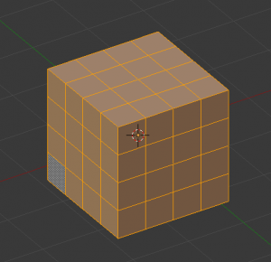
First, start with a Cube.
- Press ⇆ Tab to switch into Edit mode.
- Make sure all the vertices of the cube are selected by pressing A twice. Then, go to the Editing context by pressing F9. You should be able to see the Mesh Tools panel now.
- Subdivide the cube by pressing the Subdivide button in the Mesh Tools panel, or with W » Subdivide. You can do this as many times as you want; the more you subdivide, the smoother your sphere will be.
- Now, press ⇧ ShiftAltS and move your mouse left or right to interactively control the proportion of “spherification” (or directly type a value, like “1.000” to achieve the same effect as below) – preferably using the Median Point pivot point!
- Alternatively, you can use the To Sphere button (in the Mesh Tools panel). Select “100” to make your sphere. Note that you should not move the 3D cursor – or you won’t get a sphere, but a piece of sphere…
