「利用者:Sergof/GSoC2012/Documentation」の版間の差分
細 (1版 をインポートしました) |
|
(相違点なし)
| |
2018年6月29日 (金) 05:50時点における最新版
目次
Rigid Body Simulation
Introduction
The rigid body simulation can be used to simulate the motion of solid objects. It affects the position and orientation of objects and does not deform them.
Unlike the other simulations in Blender, the rigid body sim works closer with the animation system. This means that rigid bodies can be used like regular objects and be part of parent-child relationships, animation constraints and drivers.
Rigid Body Object
Right now only mesh objects can participate in the rigid body simulation. To create rigid bodies, either click on "Rigid Body" in the physics tab of the properties editor or use the "Add Active/Passive" buttons in the tools panel.
There are two types of rigid body: active and passive. Active bodies are dynamically simulated, while passive bodies remain static. Both types can be driven by the animation system when using the "Animated" option.
During the simulation, the rigid body system will override the position and orientation of dynamic rigid body objects. Note however that the location and rotation of the objects is not changed, so the rigid body sim acts similar to a constraint. To apply the rigid body transformations you can use the "Apply Visual Transform" operator.
The scale of the rigid body object also influences the simulation, but is always controlled by the animation system.
Properties
- Type: Role of the rigid body in the simulation. Active objects can be simulated dynamically, passive object remain static.
- Enabled: Enables/Disables simulation of the object.
- Animated: Allows the rigid body to be driven by the animation system
- Mass: Specifies how heavy the object is.
Rigid Body Collisions
General Settings
- Friction: Specifies how much velocity is lost when objects collide with each other.
- Bounciness: Specifies how much objects can bounce after collisions.
Collision Shapes
The Shape setting determines the collision shape of the object. The following shapes are available:
- Primitive shapes - these are best in terms of memory/performance but don't necessarily reflect the actual shape of the object. They're calculated based on the object's bounding box. The center of gravity is always in the middle for now.
- Box: The size per axis is calculated from the bounding box
- Sphere: The radius is the largest axis of the bounding box
- Capsule: This points up the Z-Axis.
- Cylinder: This points up the Z-Axis. The height is taken from the z-axis, while the radius is the larger of the x/y-axes.
- Cone: This points up the Z-Axis. The height is taken from the z-axis, while the radius is the larger of the x/y-axes.
- 'Mesh based shapes' - these are calculated based on the geometry of the object so they are a better representation of the object. The center of gravity for these shapes is the object origin.
- Convex Hull: Convex approximation of the object, has good performance and stability.
- Mesh: Allows to simulate concave objects, but is rather slow and unstable.
Collision Margin
The collision margin is used to improve performance and stability of rigid bodies. Depending on the shape, it behaves differently, some shapes embed it, while others have a visible gap around them:
The margin is embedded for these shapes:
- Sphere
- Box
- Capsule
- Cylinder
- Convex Hull: Only allows for uniform scale when embedded.
The margin is not embedded for these shapes:
- Cone
- Active Triangle Mesh
- Passive Triangle Mesh: Can be set to 0 most of the time.
Rigid Body Dynamics
- Enable Deactivation: Allows object to be deactivated during the simulation (improves performance and stability, but can cause glitches).
- Start Deactivated: Starts objects deactivated. They're activated on collision with other objects.
- Deactivation Velocity: Specifies the linear/angular velocity below which the rigid body is deactivated.
- Damping: Amount of linear/angular velocity lost over time.
Rigid Body World
The rigid body world holds settings that apply to all rigid bodies in the simulation.
Rigid body objects and constraints are only taken into account by the simulation if they are in the groups specified in the rigid body world.
- Group: Holds rigid bodies participating in the simulation.
- Constraints: Holds constraints participating in the simulation.
Simulation quality and timing settings:
- Speed: Can be used to speed up/slow down the simulation.
- Split Impulse: Limits the force with which objects are separated on collision, generally produces nicer results, but makes the simulation less stable (especially when stacking many objects).
- Steps Per Second: Amount of simulation steps made per second. This only influences the accuracy and not the speed of the simulation.
- Solver Iterations: Amount of constraint solver iterations made per simulation step. Increasing this makes constraints and object stacking more stable.
Cache
Specifies the frame range in which the simulation is active.
Can be used to bake the simulation. Note: Some cache features aren't available yet (like writing cache to disk).
Field Weights
The rigid body field weights can be used to limit the influence of certain force fields and gravity.
Rigid Body Constraint
Constraints (also known as joints) connect two rigid bodies. Unlike regular animation constraints, they are separate objects.
The physics constraints available in the non-game modes are meant to be attached to an Empty object. The constraint then has fields which can be pointed at the two physics-enabled object which will be bound by the constraint. The Empty object provides a location and axis for the constraint distinct from the two constrained objects. The location of the entity hosting the physics constraint marks a location and set of axes on each of the two constrained objects. These two anchor points are calculated at the beginning of the animation and their position and orientation remain fixed in the local coordinate system of the object for the duration of the animation. The objects can move far from the constraint object, but the constraint anchor moves with the object. If this feature seems limiting, consider using multiple objects with a non-physics Child-of constraint and animate the relative location of the child.
Additional parameters appear in the Physics tab of the Properties window for the selected Empty object.
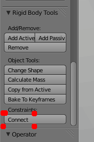
The quickest way to constrain two objects is to select both and click the Connect button in the Rigid Body Tools subtab of the 3D View's tools pop-out ('t' key). This creates a new Empty object (named Constraint) with a physics constraint already attached and pointing at the two selected objects.
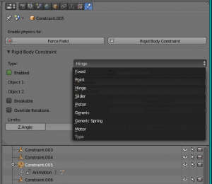
There are several constraint types available:
- Fixed - Fixes the relative position and orientation of two rigid bodies.
- Point - Constrains rigid bodies to move around a commom pivot point.
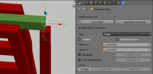
- Hinge - Only allows rotation around the Z axis of the constraint object.
- Slider - Limits movement to the X axis of the constraint object.
- Piston - Similar to slider but also allows rotation around the X axis of the constraint object.
- Generic - Allows customizable constraint axes.
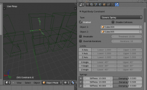
- Generic Spring - Like Generic with spring motion.
- Enabled: Specifies whether the constraint is active during the simulation.
- Disable Collisions: Allows constrained objects to pass through one another.
- Object1: First object to be constrained.
- Object2: Second object to be constrained.
- Breakable: Allows constraint to break during simulation.
- Breaking Threshold: Impulse strength that needs to be reached before constraint breaks.
- Override Iterations: Allows to make constraints stronger (more iterations) or weaker (less iterations) than specified in the rigid body world.
- Iterations: Number of constraint solver iterations made per simiulation step for this constraint.
- Limits:
- By using limits you can constrain objects even more by specifying a translation/rotation range.
- Enable: Enables limit for the specified axis.
- Lower Limit: lower translation/rotation limit.
- Upper Limit: upper translation/rotation limit.
- To lock one axis, set both limits to 0.
- Springs:
- Enable: Enables spring for the axis.
- Stiffness: Specifies how "bendy" the spring is.
- Damping: Amount of damping the spring has.
Fixed
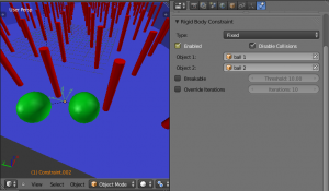
This constraint cause the two objects to move as one. Since the physics system does have a tiny bit of slop in it, the objects don't move as rigidly as they would if they were part of the same mesh.
Point
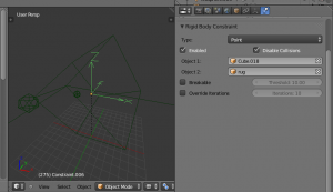
The objects are linked by a point bearing allowing any kind of rotation around the location of the constraint object, but no relative translation is permitted. The physics engine will do its best to make sure that the two points designated by the constraint object on the two constrained objects are coincident.
Hinge
The hinge permits 1 degree of freedom between two objects. Translation is completely constrained. Rotation is permitted about the Z axis of the object hosting the Physics constraint (usually an Empty, distinct from the two objects that are being linked). Adjusting the position and rotation of the object hosting the constraint allows you to control the anchor and axis of the hinge.
The Hinge is the only 1-axis rotational constraint that uses the Z axis instead of the X axis. If something is wrong with your hinge, check your other constraints to see if this might be the problem.
Slider
The Slider constraint allows relative translation along the X axis of the constraint object, but permits no relative rotation, or relative translation along other axes.
Piston
A piston permits translation along the X axis of the constraint object. It also allows rotation around the X axis of the constraint object. It's like a combination of the freedoms of a slider with the freedoms of a hinge (neither of which is very free alone).
Generic
The generic constraint has a lot of available parameters.
The X, Y, and Z axis constraints can be used to limit the amount of translation between the objects. Clamping the min/max to zero has the same effect as the Point constraint.
Clamping the relative rotation to zero keeps the objects in alignment. Combining an absolute rotation and translation clamp would behave much like the Fixed constraint.
Using a non-zero spread on any parameter allows it to rattle around in that range throughout the course of the simulation.
Generic Spring
The Generic Spring constraint adds some spring paramters for the X/Y/Z axes to all the options available on the Generic constraint. Using the spring alone allows the objects to bounce around as if attached with a spring anchored at the constraint object. This is usually a little too much freedom, so most applications will benefit from enabling translation or rotation constraints.
If the damping on the springs is set to 1, then the spring forces are prevented from realigning the anchor points, leading to strange behavior. If your springs are acting weird, check the damping.
Motor
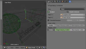
The Motor constraint causes translation and/or rotation between two entities. It can drive two objects apart or together. It can drive simple rotation, or rotation and translation (although it won't be constrained like a screw since the translation can be blocked by other physics without preventing rotation).
The rotation axis is the X axis of the object hosting the constraint. This is in contrast with the Hinge which uses the Z axis. Since the Motor is vulnerable to confusing peturbations without a matching Hinge constraint, special care must be taken to align the axes. Without proper alignment, the motor will appear to have no effect (because the hinge is preventing the motion of the motor).
Other considerations
As with all physics-enabled objects, pay close attention to the Animated check box in the Rigid Body subtab of the Physics tab in the Properties panel. A common mistake is to use keyframe animation on a Passive physics object without checking the Animated box. The object will move, but the physics engine will behave as if the Passive is still in its starting place, leading to disappointment.
Animation
The most common trick is to keyframe animate the location or rotation of an Active physics object as well as the Animated checkbox. When the curve on the Animated property switches to disabled, the physics engine takes over using the object's last known location, rotation and velocities.
Animating the strengths of various other parameters (a Motor's Target Velocity, a Hinge's limits, etc) can be used to accomplish a wide variety of interesting results.
Enabling a constraint during the physics simulation often has dramatic results as the physics engine tries to bring into alignment two objects which are often dramatically out of alignment. It is very common for the affected objects to build up enough kinetic energy to bounce themselves out of camera (and into orbit, although the physics engine is not yet capable of simulating a planet's gravity well, so scratch that).
Effectors
The rigid body simulation works with Blender's force fields, just create and use them as usual.
Simulation Stability
The simplest way of improving simulation stability is to increase the steps per second. However, care has to be taken since making too many steps can cause problems and make the simulation even less stable (if you need more than 1000 steps, you should look at other ways to improve stability).
Increasing the number of solver iterations helps making constraints stronger and also improves object stacking stability.
It's best to avoid small objects, as they're currently unstable. Ideally, objects should be at least 20 cm in diameter. If it's still necessary, setting the collision margin to 0, while generally not recommended, can help making small object behave more naturally.
When objects are small and/or move very fast, they can pass through each other. Besides what's mentioned above it's also good to avoid using mesh shapes in this case. Mesh shapes cosist of individual triangles and therefore don't really have any thickness, so objects can pass through more easily. You can give them some thickness by increasing the collision margin.
Combining Rigid Bodies with Other Simulations
Since the rigid body sim is part of the animation system, it can influence other simulations just like the animation system can.
In order for this to work, the rigid body object needs to have a collision modifier. Simply click on "Collision" in the Physics tab.
Scaling Rigid Bodies
Rigid body objects can be scaled, also during the simulation. This work well in most cases, but can sometimes cause problems.
If dynamic scaling is not needed, rigid body objects should have the scale applied by using the "Apply Scale" operator.
There are a few (somewhat outdated) demo/tutorial videos:
