「Doc:2.6/Tutorials/Your First Animation/1.A static Gingerbread Man」の版間の差分
(→SubSurfaces (Subsurf): corrected sentence structure) |
細 (1版 をインポートしました) |
(相違点なし)
| |
2018年6月29日 (金) 03:45時点における最新版
目次
Your First Animation in 30 plus 30 Minutes Part I
This chapter will guide you through the animation of a small "Gingerbread Man" character. We will describe each step completely, but we will assume that you have read the interface chapter, and that you understand the conventions used throughout this book.
In Part I of this tutorial we'll build a still Gingerbread Man. Then, in Part II, we will make him walk.
Note
For a much more in-depth introduction to Blender that focuses on character animation, check out the
Blender Summer of Documentation Introduction to Character Animation tutorial (this is written for V2.4x but still can be very instructive).
|
Warming up
After starting Blender, you should see the Default screen set up. The 3D view in the centre displays a camera, a light, and a cube. The cube should already be selected, as indicated by its orange outline.
We will start by organizing our working area by placing Objects on different layers. 3D scenes can quickly become confusing when multiple Objects are on the screen. With layers, you can hide Objects you aren't working on and make them visible when you need them.
Blender provides you with twenty layers to help organize your work. You can see which layers are currently visible from the group of twenty buttons in the 3D window header (see Layer visibility controls). You can change the visible layer with LMB ![]() and manage the visibility of multiple layers with ⇧ ShiftLMB
and manage the visibility of multiple layers with ⇧ ShiftLMB ![]() . Visible layers are indicated by a darker gray color in the layer visibility controls. The last layer that is made visible becomes the active layer. The active layer is also where all new Objects will be stored.
. Visible layers are indicated by a darker gray color in the layer visibility controls. The last layer that is made visible becomes the active layer. The active layer is also where all new Objects will be stored.
Read more about layers »
Let's clean up the screen by first moving the camera and lamp to another layer.
Select the Camera with RMB ![]() . Then add the Lamp to the selection with ⇧ ShiftRMB
. Then add the Lamp to the selection with ⇧ ShiftRMB ![]() . Press M and a small toolbox, like the one in (The Move to Layer popup) will appear beneath your mouse with the first button checked. This means that the selected objects are stored in layer 1. Click the rightmost button on the top row. This will move your Camera and Lamp to layer 10.
. Press M and a small toolbox, like the one in (The Move to Layer popup) will appear beneath your mouse with the first button checked. This means that the selected objects are stored in layer 1. Click the rightmost button on the top row. This will move your Camera and Lamp to layer 10.
Keyboard Shortcuts
Blender is mainly controlled with lots of keyboard shortcuts (don't panic, you'll get used to it). Most of those shortcuts only work while the mouse pointer hovers above the corresponding frame. So don't get frustrated if M doesn't do what it's supposed to do -- just move the mouse into the 3D view.
|
Now make sure that only Layer 1 is visible (colored a darker gray in the layer visibility controls) so that we can start modeling.
Building the body
With Num lock activated, change to the front view with 1 NumPad and to orthogonal view with 5 NumPad. The upper left corner of the 3D window will tell you whether you are in orthogonal or perspective view.
If you don't have a Cube on your screen we'll need to add one. Snap your cursor to the center (0,0,0) of the screen by Object » Snap » Cursor to Center or using the ⇧ ShiftS shortcut.
Then add a Cube with Add » Add Mesh » Cube or using the ⇧ ShiftA shortcut. A cube will appear displayed in orange to indicate that it is the active Object. Press ⇆ Tab to enter Edit Mode.
Edit Mode is a mode in which you can edit the vertices of the mesh. By default, all vertices are selected for every new Object created (selected vertices are highlighted in orange, unselected vertices are black). In Object Mode, vertices cannot be selected or edited individually; the Object can be changed only as a whole. You can press ⇆ Tab to switch between these two modes. The current mode is indicated in the header of the 3D window.
We will call our Gingerbread man "Gus". To do so, switch to the object-context (See Naming Gus) which can be found on the Properties Window on the right hand side. You can rename Gus on the first line.
Our first task is to build Gus's body by working on the vertices of our cube. Tools to do this can be found on the Tool Shelf, which is a part of the 3D Window (on the left hand side of the screen). If you can't see the Tool Shelf, simply press T.
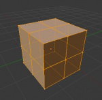
Now locate the Subdivide button in the Tool Shelf (under Add) and press it once. This will split each side of the cube in two, creating new vertices and faces. The result is illustrated below. If you want to get the same view, change to perspective with Num5 and rotate the view by clicking and dragging with MMB ![]() . Don't forget to change the view back with Num1 (Front View) and Num5 (Perspective/Orthographic).
. Don't forget to change the view back with Num1 (Front View) and Num5 (Perspective/Orthographic).
With your cursor hovering in the 3D window, press A to deselect all elements. Vertices will turn black.
You must have the Limit Selection to Visible button ![]() unselected to continue this tutorial.
unselected to continue this tutorial.
Now press B to activate Box Select/Border Select mode. The cursor will change to a couple of orthogonal grey lines. Move the cursor above the top left corner of the cube, press and hold LMB ![]() , then drag the mouse down and to the right so that the grey box encompasses all the leftmost vertices. Now release the LMB
, then drag the mouse down and to the right so that the grey box encompasses all the leftmost vertices. Now release the LMB ![]() .
.
Press X, and from the popup menu select Vertices to erase the selected vertices.
Another tool to select or deselect vertices is Circle Select, which can be activated by pressing C. When the Circle Select tool is active, clicking or dragging with LMB ![]() selects vertices. MMB
selects vertices. MMB ![]() deselects vertices. Using the mouse-wheel changes the size of the selection-circle. RMB
deselects vertices. Using the mouse-wheel changes the size of the selection-circle. RMB ![]() or ↵ Enter finalizes the selection and exits Circle Select mode. Just give that alternative a try after you deleted the vertices as mentioned above.
or ↵ Enter finalizes the selection and exits Circle Select mode. Just give that alternative a try after you deleted the vertices as mentioned above.
Mirror modelling
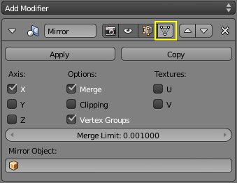
To model symmetrical objects we can use the Mirror modifier. It allows us to model only one side of Gus while Blender creates the other in real time. Go to the Properties editor and find the Modifiers context.
It is pretty empty for the moment. Clicking the button marked Add Modifier opens a list where you can choose Mirror.
In addition to affecting Objects in a non-destructive manner, modifiers also allow you to control what is displayed when you are working with them. In our case we will check the Cage Mode button so we can see the transparent mirrored faces in Edit Mode.
We then choose the axis to mirror Gus along by checking either the X, Y or Z button. The mirror plane will be perpendicular to that axis. In our case it is the X-axis.
The Merge button will merge any mirrored vertices that are equal to or closer than the distance specified by the Merge Limit slider. Essentially any mirrored vertex closer to the mirror plane than the limit we set will be placed exactly on the mirror plane and merged with the corresponding vertex. The limit can be set from 0.000 to 1.000 units and how big it should be depends on the nature and the scale of the current job.
For modeling Gus, a vertex that is more than 0.1 units away from the mirror plane would be noticeable but anything closer might not be visible. To prevent a large rip showing up in the middle of our mesh or cause us to neglect a wandering vertex, we should set the Merge Limits to 0.1.
Finally, with the Clipping button checked, the mirror plane becomes a border that no vertex can cross. Also, when Clipping is active, every vertex that is on the mirror sticks to it.
As you can see, the Mirror modifier gives us a lot of features to make our lives easier.
Arms and Legs
Let's create Gus's arms and legs. Using the sequence you just learned, Box Select the two top-right-most vertices (Extruding the arm in two steps), which will actually select the other four behind them, for a total of six vertices. Press E to extrude them (or use the Extrude Region button in the Tool Shelf). This will create new movable vertices and faces which you can move with the mouse. Move them one and a half squares to the right, then click LMB ![]() to fix their position. Extrude again with E then move the new vertices another half a square to the right. The image below shows this sequence.
to fix their position. Extrude again with E then move the new vertices another half a square to the right. The image below shows this sequence.
Undo/Redo
Blender has two Undo features, one for Edit Mode and the other for Object Mode.
In Edit Mode press CtrlZ to Undo and keep pressing CtrlZ to roll back changes as long as the Undo buffer will allow; ⇧ ShiftCtrlZ re-does changes. On Macs use ⌘ Cmd instead of Ctrl.
Two things to remember:
- Undo in Edit Mode works only for the Object currently in that mode.
- Undo data is not lost when you switch out of Edit Mode, but it is as soon as you start editing a different Object in Edit Mode.
In Object Mode the same shortcuts apply. CtrlZ to undo, ⇧ ShiftCtrlZ to redo. If you made changes in Edit Mode that are not lost for that Object, they will all be undone in one single shot with CtrlZ when this step has its turn.
If you change your mind in the middle of an action, you can cancel it immediately in many cases and revert to the previous state by pressing Esc or RMB ![]() .
.
Coincident vertices
Extruding works by first creating new vertices and then moving them. If in the process of moving you change your mind and press Esc or RMB ![]() to cancel, the new vertices will still be there, on top of the original ones! The simplest way to go back to the state before you started extruding is to Undo (CtrlZ). It is sometimes useful to intentionally create new vertices this way and then move, scale or rotate them by pressing G,S or R.
to cancel, the new vertices will still be there, on top of the original ones! The simplest way to go back to the state before you started extruding is to Undo (CtrlZ). It is sometimes useful to intentionally create new vertices this way and then move, scale or rotate them by pressing G,S or R.
Gus should now have a left arm that you modeled (he's facing us) and a right arm that Blender added. We will build the left leg the same way by extruding the lower vertices three times. Try to produce something similar to the Body image shown to the right. If you are using Extrude - Region, you will have to temporarily turn off the Mirroring modifier by unchecking the X option under Axis, and rechecking it after extruding (otherwise Gus will end up with a skirt rather than pants).
You can free the movement of the extruding vertices by clicking MMB ![]() after you have pushed E but before you click LMB
after you have pushed E but before you click LMB ![]() . If you do not do this your legs will end up going straight down, rather than down and to the side as pictured in Body.
. If you do not do this your legs will end up going straight down, rather than down and to the side as pictured in Body.
Tip: If you want to position exactly, hold down Ctrl while moving things around.
We're done with mirror modeling. In the next steps we will experiment with other techniques. We need to make the right part of our model real since nothing done with modifiers is permanent unless we apply the changes. With Gus being in Object Mode (press ⇆ Tab if he's still in Edit Mode), click on the Apply button of the Mirror modifier.
The Head
Gus needs a head.
Change back to Edit Mode (press ⇆ Tab)
Move the cursor to exactly one square above Gus's body. To place the cursor at a specific grid point, LMB ![]() click to position the cursor near where you want it and then press ⇧ ShiftS to bring up the Snap Menu. Cursor to Grid places the cursor exactly on a grid point. That's what we want right now. Cursor to Selection places it exactly on the selected object, which is sometimes handy.
click to position the cursor near where you want it and then press ⇧ ShiftS to bring up the Snap Menu. Cursor to Grid places the cursor exactly on a grid point. That's what we want right now. Cursor to Selection places it exactly on the selected object, which is sometimes handy.
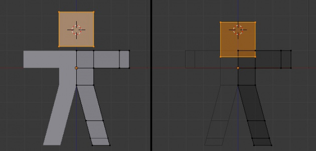
Add a new cube for Gus' head (⇧ ShiftA >> Add >> Cube) (leftmost image of Adding the head).
Object Creation
When you add an object while in Edit Mode for another object, the new object becomes part of the existing object. So by adding this cube while we have Gus' body in edit mode, it's automatically part of him.
|
Now press G to switch to Grab Mode and move the newly created cube down. You can constrain the movement to a straight line by moving the head down a bit and then clicking MMB ![]() . Move Gus' new head down about one third of a grid unit then press LMB
. Move Gus' new head down about one third of a grid unit then press LMB ![]() to fix its position (rightmost image of Adding the head.).
to fix its position (rightmost image of Adding the head.).
SubSurfaces (Subsurf)
For the next step, we'll need to select all of Gus, and not just his head (use A - maybe twice).
So far what we have produced is a rough figure at best. To make it smoother, locate the Modifier context and add a Subdivision Surface modifier, (The Subsurf modifier). Be sure to set both the View and Render NumButtons (located under Subdivisions) to values at or below 2. View sets the level of subdivision you'll see in the 3D viewport; Render sets the level of subdivision used by the renderer.
SubSurfaces
SubSurfacing is an advanced modelling tool that dynamically refines a coarse mesh. It works by creating a much denser mesh and locating the vertices of this finer mesh so that they follow the original coarse mesh smoothly. The shape of the object is still controlled by the location of the coarse mesh vertices, but the rendered shape is a finely smooth mesh.
|
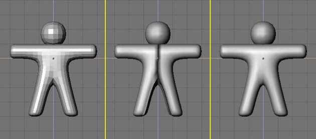
To have a look at Gus, switch out of Edit Mode (⇆ Tab) and to Solid display mode using Z (in the case it isn't active). He should look like (Setting Gus to smooth).
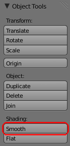
To make smooth Gus look even smoother, press the Smooth button found under Shading in the Tool Shelf of the 3D Window (T). Gus will now appear smooth, although he may wear some funny black lines in his middle. This is usually avoided if you used the Mirror modifier, but it might happen when extruding and flipping as was done before the Mirror modifier was introduced (Setting Gus to smooth., middle). These lines appear because the SubSurf's finer mesh is computed using information about the coarse mesh's normal directions (the direction perpendicular to a face), which may not all point in the right direction (some face normals might be pointing outward and some pointing inward). To reset the normals, switch back to Edit Mode (⇆ Tab), select all vertices (A), and press CtrlN (recalculate vertex normals to point outside). Now Gus should be nice and smooth (Setting Gus to smooth, right).
Press MMB ![]() and drag the mouse around to view Gus from all angles. Oops, he is too thick!
and drag the mouse around to view Gus from all angles. Oops, he is too thick!
Constrained Scaling
Let's make Gus thinner:
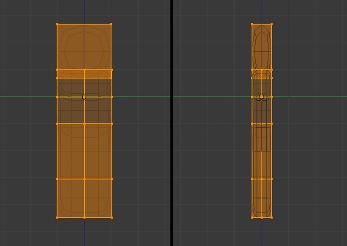
- Switch to Edit Mode if you are not there already (⇆ Tab), then back to Wireframe mode. (Z), Switch to side view using Num3 and select all vertices with A. You can do the following steps just as well in Object Mode, if you like.
- Press S and start to move the mouse horizontally. (Click MMB
 to constrain scaling to just one axis or press Y to obtain the same result). If you now move the mouse toward Gus he should become thinner but remain the same height.
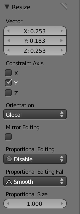
- The tab Resize on the Tool Shelf shows the scaling factor. Press and hold Ctrl in order to change the scale factor in discrete steps of 0.1. Scale Gus down so that the factor is 0.2, then confirm this dimension by clicking LMB
 . If that last transformation went wrong, you can still change its parameters. They are displayed and editable at the already mentioned place (see Parameters of the last action in the Tool Shelf).
- Return to Front view (Num1) and to Solid mode (Z), then rotate your view via MMB
 . Gus is much better now!
Let's see what Gus looks like
We're just about ready to see our first rendering, but first, we have some work to do.
- Switch to Object Mode if not already there (⇆ Tab).
- ⇧ ShiftLMB
 on the top right small button of the layer visibility buttons in the 3DWindow toolbar (Making both layer 1 and 10 visible.) to make both Layer 1 (Gus's layer) and Layer 10 (the layer with the camera and the lamp) visible.
A Tip
Remember that the last layer selected is the active layer, so all subsequent additions will automatically be on layer 10.
|
- Press N to bring up the Properties Shelf and find the Transform panel there (The Transform Panel). The location is specified by the X,Y,Z values.
- Select the camera (RMB
 ) and move it to a location like (x=7, y=-10, z=7). Do this by pressing G and dragging the camera. You may need to change views and move the camera a second time to adjust all three coordinates. If you prefer to enter numerical values for an object's location you can do so by clicking LMB
  on a Value and then entering the desired value.
Camera setup
To make the camera point at Gus, keep your camera selected then select Gus via ⇧ ShiftRMB ![]() . The camera should be dark orange (selected) and Gus light light orange (selected and active). Now press CtrlT and select the TrackTo Constraint entry in the pop up. This will force the camera to track Gus and always point at him. This means that you can move the camera wherever you want and be sure that Gus will always be in the center of the camera's view.
. The camera should be dark orange (selected) and Gus light light orange (selected and active). Now press CtrlT and select the TrackTo Constraint entry in the pop up. This will force the camera to track Gus and always point at him. This means that you can move the camera wherever you want and be sure that Gus will always be in the center of the camera's view.
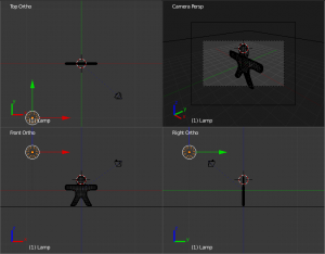
(Camera position with respect to Gus) shows top, front, side and camera view of Gus. To obtain a camera view press 0 NumPad or select View>>Camera. To get a Quad View as shown in the picture, press CtrlAltQ or select View>>Quad View.
The Ground
Now we need to create the ground for Gus to stand on.
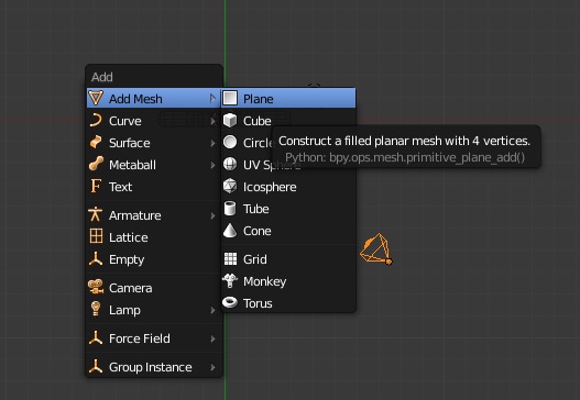
- In top view (7 NumPad or View>>Top), and in Object Mode, add a plane
- Add a plane (⇧ ShiftA or >>Add>>Mesh>>Plane).
Note
It is important to be out of Edit Mode, otherwise the newly added object would be part of the object currently in Edit Mode, as when we added Gus' head.
|
- Switch to Front view (1 NumPad or View>>Front) and move (G) the plane down to Gus's feet, using Ctrl to keep it aligned with Gus.
- Go to Camera view (0 NumPad or View>>Camera) and, with the plane still selected, press S to start scaling.
- Enlarge the plane so that its edges extend beyond the camera viewing area, as indicated by the lighter area in the camera view.
Lights
Now, lets add some light!
- In Top view (7 NumPad), move the existing Lamp light (if you do not have a Lamp light in your scene you can add one with ⇧ ShiftA >>Add>>Lamp>>Lamp) in front of Gus, but on the other side of the camera; for example to (x= -9, y= -10, z=7) (Inserting a Lamp.).
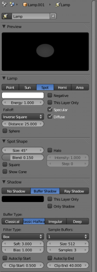
- When the lamp is selected in Object Mode, select the Object Data icon in the properties window (looking like a small sun). You will see a Lamp submenu, with Point, Sun, Spot, Hemi, and Area choices. (The object data button of a lamp).
- In the Properties Window Lamp Panel, press the Spot toggle button to make the lamp a Spotlight (The Spot light settings.) of pale yellow (R=1, G=1, B=0.9) by clicking on the white button, which is actually a color picker. Adjust Size under Spot Shape to about 40 and Blend: to 1.0.
- Make this spotlight track Gus just as you did for the camera by selecting Spot, ⇧ Shift, then Gus, then by pressing CtrlT>>TrackTo Constraint.
- Add a second lamp that provides more uniform fill light (⇧ ShiftA >>Add>>Lamp>>Hemi). Set its Energy to 0.2 (Hemi lamp settings). Move it a little above the camera (x= 7, y= -10, z=9) and set it to track Gus as before.
Two lamps?
Use two or more lamps to help produce soft, realistic lighting, because in reality natural light never comes from a single point.
|
Rendering
We're almost ready to render. As a first step, press the Render context button in the Properties window header (The Render context button).
We will use the default rendering settings, as shown in (The Render context).
Now press the Image button or F12. The result, shown in (Your first rendering. Congratulations!), is actually quite poor. We still need materials, and lots of details, such as eyes, and so on.
When you're done looking, press F11 to hide the render view.
Saving our work
If you have not done so already, now would be a good time to save your work, via the File>>Save menu shown in The Save menu.' or CtrlS. Blender will warn you if you try to overwrite an existing file.
Blender does automatic saves into your system's temporary directory. By default, this happens every five minutes and the file name is a number. Loading these saves is another way to undo unwanted changes.
Materials and Textures
It's time to give Gus some nice cookie-like material.
- Select Gus. Then, in the Properties Window header, select the Materials button (The Material context Button.) to access the Material panels.
- The Properties window will be almost empty because Gus has no materials yet. To add a material, click on the + New button in the Material Panel (The (almost) empty Material context).
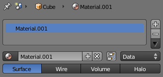
- The Properties window will then be populated by Panels and Buttons. A string holding the Material name, generally "Material.001", will appear in the list box as well as in the Unique Datablock ID box. Click the name in the latter (in the lower part of Top of the filled material contextand change it to something meaningful, like "GingerBread" (don't type the quotes).
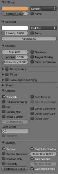
- Modify the default values as per (A first gingerbread material) to obtain a first rough material. Note that you may have to expand some panels by clicking LMB
 on the small triangle besides their header.
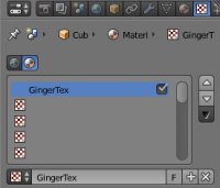
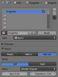
- Press the Texture context Button in the Properties window header (The Texture context button) and select Add new. We're adding a texture in the first channel. Call it "GingerTex."
- Change the Type from Clouds to Stucci and set all parameters as in (The Texture context).
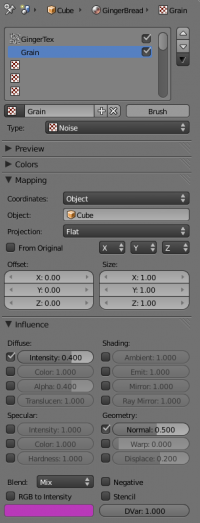
- Set the Mapping and Influence panel of the Texture context as in (Settings for the Stucci texture): Deselect the Color Checkbox and set the Normal Checkbox, then change the Normal slider to 0.75. These changes will make our Stucci texture act as a "bumpmap" and make Gus look more biscuit-like.
- Now select the second line in the Texture list of the Texture context and add a second texture. Name it "Grain", and adjust the settings to match (Settings for an additional Noise texture ). The texture itself is a plain Noise texture.
- Give the ground an appropriate material, such as the dark blue one shown in (A very simple ground material). Feel free to choose your favorite shade of blue.
Eyes and detail
To give some finishing touches we'll add eyes and some other details.
- First make Layer 1 the only one visible by clicking with LMB
 on the layer 1 button (Layer visibility). This will hide the lamps, camera, and ground.
- Place the cursor at the center of Gus's head. (Remember that you are in 3D so be sure to check at least two views to be sure!)
- In Object Mode, add a sphere ( ⇧ ShiftA >>ADD>>Mesh>>UVsphere). Press F6 and change the number of segments (meridians) to 16. You can see the result under 1 in Creation of the eyes.
- Scale the sphere down (S) to a factor of about 0.15 in all dimensions, then switch to side view (3 NumPad) and scale it only in the horizontal direction (Y) a further 0.5 (see the images 2 and 3 in Sequence for creation of the eyes).
- Zoom a little if necessary via + NumPad, Wheel
 , or CtrlMMB
  , and drag the sphere (G) to the left so that it is halfway into the head, as shown in image 4 of Creation of the eyes.
- Return to front view (1 NumPad) and move the sphere sideways, to the right. Place it where Gus should have an eye (picture 5 in Creation of the eyes).
Flipping a duplicate around the cursor
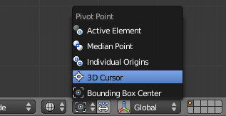
- Switch to Edit Mode (⇆ Tab). Select the crosshair pivot button (pivot: 3D Cursor)in the header of the 3D window (the 3D Transforms Manipulator jumps from the sphere to the cursor). All vertices of the eye should be selected (if not, press A to select all), now press ⇧ ShiftD or use Duplicate in the Tool Shelf to duplicate and Esc to stop placing the copy with the mouse.
- Press CtrlM to mirror, X to mirror around the X axis, followed by LMB
 or ↵ Enter to confirm the mirror. Return the pivot button to its default setting ( Median Point). The result can be seen in picture 6 of Creation of the eyes.
Mirroring
Mirroring is also possible in object mode using CtrlM.
|
Now Gus has two eyes.
Mouth
- Exit Edit Mode (⇆ Tab), and place the cursor as close as you can (remember the ⇧ ShiftS key) to the center of Gus's face. Add a new sphere and scale and move it exactly as done before for the eyes, except make its allover scale smaller (0.1 instead of 0.15). Place it below and to the right of the cursor, centered on the SubSurfed mesh vertex, as shown in picture 2 of Creating a mouth with the Spin tool.
- Switch to Edit Mode (⇆ Tab). Now use AltR or LMB
 on Spin on the Tool Shelf. Several copies of the sphere appear.
- On the lower Tool Shelf, (Press F6 if not visible), set the details of the Spin: Set Degr: to 90, Steps: to 3. The result should be Gus's mouth, like image 3 in Creating a mouth with the Spin tool.
(EDIT REMARK: The properties of the last command (as Spin in the above descriptions) don't show in every 3D window (at least in the editors Version of Blender (V2.5 beta, Mac)) so don't panic - it is there somewhere (at least in the default screen))
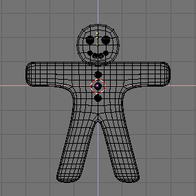
- Now go back to Object Mode and add three more spheres (below the head and centered along the Z-axis) to form Gus's buttons. Once you have made one button, you can simply exit Edit Mode, press ⇧ ShiftD to create a duplicate, and move the duplicate into place, as shown in The complete Gus!.
Attaching the spheres
If we want to be able to grab Gus and move him around as a whole (this goes beyond the animation in the second part of this tutorial), we now need to attach the small spheres representing eyes, mouth, and buttons to the body. Enter Object Mode and press A until nothing is selected. Now right click one sphere (if more than one is selected as a group, that's ok). Holding ⇧ Shift, select the body. Then hit CtrlP and left click Object on the pop up. Deselect everything and repeat the process to attach each element.
|
Eyes material
Give the eyes a chocolate-like material. Give the mouth a white sugar-like material, and Gus's buttons could use a bit of color too. Remember what you did when giving a material to Gus himself and be a bit creative; soon Gus will show top-notch gingerbread fashion.
Objects sharing a material
To give one object the same material as another object (i.e. reusing the white material of the mouth on one of the buttons), select that material in the Material Menu list which appears when you press the button Browse ID Data besides the Data Block ID Name in the Material context of the Properties window (In Material context the checkered little sphere shown besides Material.001 is what you need).
|
Rendering
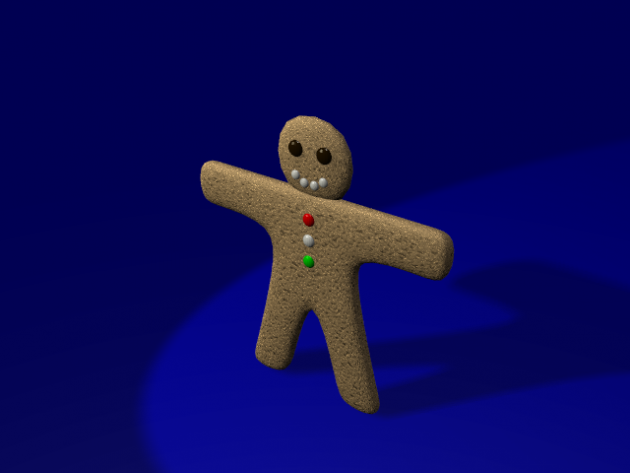
Once you have finished assigning materials, make layer 10 visible again (remember how? Hint, look at the 3D window header), so that lights and the camera also appear, and do a new rendering (F12).
The result should look more or less like (The complete Gus still rendering).
Saving
Save your image by using F3 in the UV/Image Editor that is showing the render result. Enter the name of your image in the file window, choose a destination and save.
You can choose the image format (JPEG, PNG, and so on) by setting it in the shelf to the right of the File Browser.
Blender adds an extension to the file name; as you are probably used to (this is new in V2.5, in V2.4x you had to do it manually).


