「利用者:Samrage/Sandbox」の版間の差分
細 (1版 をインポートしました) |
|
(相違点なし)
| |
2018年6月29日 (金) 04:39時点における最新版
Extrusão do restante da face
Agora que a boca está espelhada como modificador Mirror, e suavizada com Set Smooth e Subsurf, iremos modelar o restante da face. Basicamente, iremos efetuar extrusões e ajustes no tamanho e na forma da malha de vértices. Por enquanto, vamos trabalhar com o modificador Subsurf desativado no Modo de Edição.
Loop Selection - Seleção em Laço de faces e arestas
AltRMB ![]() para selecionar um loop de arestas
para selecionar um loop de arestas
⇧ ShiftAltRMB ![]() para adicionar um loop de arestas à seleção
para adicionar um loop de arestas à seleção
CtrlAltRMB ![]() para selecionar um loop de faces
para selecionar um loop de faces
⇧ ShiftCtrlAltRMB ![]() para adicionar um loop de faces à seleção
para adicionar um loop de faces à seleção
Mais informações: Manual/PartII/Edge_and_Face_Tools
- Primeiro, use AltRMB
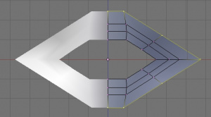
 no "edge loop" (laço de vértices) na extremidade da malha. Isso irá selecionar todos os vértices e arestas que compõe o loop (conforme a imagem Loop de arestas selecionado).
|
Se você estiver usando o Gnome, na configuração padrão, será necessário usar outros metodos de seleção. Alternativamente, alguns gerenciadores de janelas irão ignorar o Alt+clique se outra tecla estiver pressionada; tente manter pressionado as teclas Windows (Meta) e Alt (clicando com o botão direito do mouse) ao mesmo tempo. Você também pode configurar seu gerenciador de janelas para usar outra tecla (que não o Alt) para mover janelas.
|
Agora vamos à extrusão do loop de arestas.
- 3 NumPad para Visão Lateral.
- O para desativar a Edição Proporcional por enquanto.
- E para Extrude >> Only vertices.
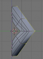
- Mova os novos vértices criados um pouco para trás (como na imagem Extrusão do Loop de vértices para trás).
- LMB
 para confirmar o movimento.
 - Com os vértices recém-extrudados ainda selecionados, pressione S para escalonar o novo loop, aumentando-o, e LMB
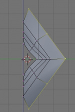
 para confirmar (como na imagem Escalonando o loop de vértices).
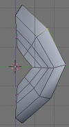
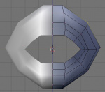
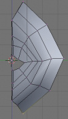
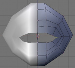
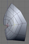
- Enable proportional editing again with O, and give the face some shape by moving around some vertices with G. Use both Front View (1 NumPad) and Side View (3 NumPad) to shape the face (see two images below).
- After you're done shaping, disable proportional editing again with O.
- Just like you did above, extrude the outer edge twice more for a total of three times.
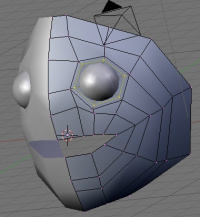
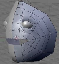
The images below show the results of a couple minutes of shaping the mesh. Note how I closed the mouth and gave the face some shape.
This is where you can give your character some, well, character. I'm going to keep it simple in order to focus on the tools rather than the modeling. For example, I'm not going to worry about making a nose or ears for this character. Since you move the mouse differently than I do and will therefore shape the face differently than me, from here on out the model in this tutorial might look a little different from yours.
Making room for the eyes
The mesh will take a little prep work to make the eye fit properly. Here are the steps I took to make an eye socket:
- Make a loop cut (CtrlR and MMB
 ) as in Loop-cutting for the eye socket. This will give us some more vertices to work with.
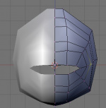
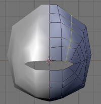
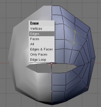
 - Select the two vertices as shown in Deleting edge. Pay attention to the menu: this time, instead of deleting the selected vertices, we'll delete the selected edge. You do this by choosing X>>Edges. The vertices will remain, but the edge connecting them as well as the faces containing the edge, will be deleted.
- This makes a hole in the mesh
Deleting
After pressing X to delete, you can select which part of the selection to delete from the menu.
- Vertices will delete the vertices, as well as any faces or edges containing those vertices.
- Edges will delete the edges and any faces containing those edges, but will leave vertices alone.
- Faces will delete just the faces and will leave edges and vertices alone
- All will get rid of everything in the mesh - including unselected regions!.
- Edges & Faces will leave you with a bunch of vertices floating in space.
- Only Faces will leave you a wireframe, without any faces.
- Edge Loop, which is a fairly new feature, is a great tool - it will remove an entire edge loop, and weld the adjacent edge loops together.
Adding an eye
Let's add an eye. We want the eye to be separate from the face, so it can rotate freely. This won't be possible if we add vertices to the exisiting mesh. Instead, we will add another mesh object.
- Switch to Object Mode (⇆ Tab).
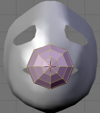
- Add a UV Sphere (Space>>Add>>Mesh>>UV Sphere). More info on mesh types can be found at Manual/PartII/Basic_Objects. To save yourself work, use the mesh type that best matches the object you're trying to model. I chose a UV Sphere instead of an icosphere because it will be easier to make the pupil using the UV Sphere's rings.
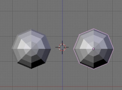
- You will be prompted for the number of Segments and Rings. Change both Segments and Rings to 8. You can either click the arrow buttons or LMB
 on the number box to type in a value. You can use however many Segments and Rings you'd like; in this case I'm using 8. We can always subsurf it to make it look as smooth as we want. If the UV sphere has too many vertices, it may get difficult to work with. The default of 32 is too many - we don't need that kind of complexity for an eye.
`
- Adding a mesh automatically puts you in Edit Mode. Switch back to Object Mode (⇆ Tab). We need to move the eye (it's clearly not in the right spot!), but if you move the vertices of the eye while in Edit Mode, the Object Center will stay where it was created. For reasons that will become clear later, we want the Object Center to remain in the center of the eye, so we have to switch Object Mode to move the object as a whole.
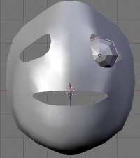
- Use G to position and S to scale the eyeball to where you ultimately want it to be. You'll need to change the view quite a bit to get the right size and location. In subsequent steps, we'll make the face mesh fit the eye - so don't worry about any gaps now between the eye and the eyelids.
- The result should look something like Positioning the eye.
- Just like we did for the face, use Set Smooth (in the Edit Buttons) and add a Subsurf modifier to make the eye smooth.
Duplicating and Mirroring the eye
.
When you're happy with where the eye is, then we can make a duplicate and mirror it across the X-axis. However, we will not use a Mirror modifier for this. Why not?
Well, we don't want to mirror the eye in order to model it symmetrically. It's already symmetrical. Instead, we want a separate object for the other eye so that the eyes can move around independently of each other. It's certainly possible to add another UV Sphere and position it and scale it exactly the same way as we just did, but there's an easier and more powerful way to make a second eye.
- Make sure you're in Object Mode.
- Make sure the 3D cursor is in the middle of the face. If you haven't moved it, it should still be there. If not,
- Select the face mesh
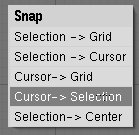
- Use the Snap tool ⇧ ShiftS>>Cursor to Selection to snap the cursor to the center of the face (The Snap menu).
- Select the eye.
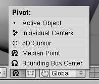
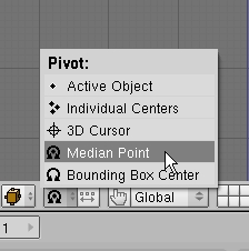
- From the Pivot Center menu at the bottom of the 3D Window (Pivot center menu), select 3D cursor. This will change the reference point to the 3D Cursor. The default was the median point of all items selected. In other words, we're forcing the center of rotation or the center of mirroring to be wherever the 3D Cursor is.
- With the eye still selected, use ⇧ ShiftD to Duplicate the eye. Just like in extruding, Grab mode is automatically activated. Try moving the mouse to see that we now have a duplicate eye.
- RMB
 to cancel the automatic move mode. Just like extruding, the duplicate object is still there, even though we cancelled the move. The duplicate eye is still selected, and it's right on top of the original eye.
- CtrlM>>X Local to mirror the duplicated eye.
- From the Pivot Center menu (Pivot center menu), go back to the default mode, Median Point.
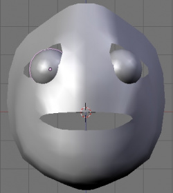
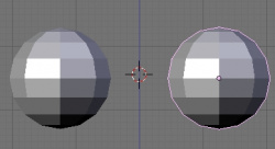
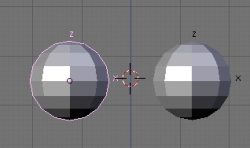
- It should now look something like Mirrored, duplicate eye. The duplicate eye has been mirrored across the plane of the 3D Cursor, and there was no annoying moving and scaling to deal with.
Move the eyes to a different layer
Up until adding the eyes, we only had one object to worry about (the face). Now, to make things easier later down the road, we'll move the eyes to a different layer. You access Blender's layer system either with the matrix of buttons in the bottom of the 3D Window (Layer buttons), or with the number keys on the top row of the keyboard. The default scene had only Layer 1 active, so the face and the eyes were both added to Layer 1.
Let's move the eyes to Layer 2.
- Press ` (the ~ key, to the left of the 1 key) to view all layers. Note how the Layer buttons all turn dark, indicating they are all selected (All Layers selected.]]
- Access the Move To (layer) menu with M (The Move To menu).
- Either press 2 or click the button for Layer 2, as shown in The Move To menu.
- Either press ↵ Enter or the OK button to confirm. Simply moving the mouse cursor away from the menu will cancel the move.
- Do the same thing with the face, to make sure it is on Layer 1 (Select the face, M, 1, ↵ Enter).
- To view just the eyes, press 2, or click the Layer 2 button in the Layers buttons. To view just the face, press 1, or click the Layer 1 button in the Layers buttons.
- To view multiple layers, use ⇧ Shift: 1, then ⇧ Shift2 will show both Layer 1 and Layer 2. Alternatively, hold ⇧ Shift while clicking the Layer buttons.
Adjusting the axes of the eyes
Mirroring the eyes across the X-axis was a useful way of making sure they were symmetrical. However, it also made the axes of the eyes different from each other. Later on when we add Track To constraints, we'll want the axes of both the eyes to be identical (this will become clearer later).
- View Layer 2 alone by using 2.
- Select one of the eyes.
- Clear the rotation of the object with AltR. This resets the rotation so the axes of the eyes are pointing straight up, so we're all on the same page.
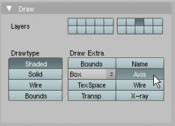
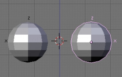
- Under the Object buttons in the Buttons window, look for the Draw panel and press the Axis button. This draws the axes (X,Y, and Z) for this object.
- Select the other eye and enable drawing of the axis for it as well.
- Notice how the Z axis is pointing up for both eyes, but the X-axis points to the left in one eye and to the right in the other eye. The reason this happened is that we mirrored the second eye across the X-axis - so the new X-axis direction is a mirror image of the orginal one. We want both X-axes pointing the same way. To do this, we will mirror the second eye in place instead of across the 3D Cursor like we did earlier.
- Select the second eye.
- Make sure the Pivot center is set to Median Point.
- Mirror the second eye in place with CtrlM>>X Local. Now the X-axes of both eyes point the same way.
Next, we want to rotate the eyes so that the "poles" are pointing forward so we can easily make the pupils of the eyes. We want to leave the axis alone, since we just fixed it. To rotate the eye without changing the object's axis, we need to enter Edit mode.
- Select an eye and enter Edit mode.
- Switch to Side view (3).
- Select all vertices with A (you may have to hit it twice).
- Rotate the vertices 90 degrees with R-9-0-↵ Enter.
- Switch to Object mode, select the other eye, and rotate it 90 degrees in Side view as well (it may be hidden behind the other eye, that's OK - your rotation commands will still work or you could switch to left side view with Ctrl3 NumPad so you can see the left eye).
OK, we've rotated the eyes correctly to compensate for the mirroring and made their poles point toward the front. Make sure you're viewing both the eyes and the face for the next series of steps (remember, ` views all layers).
Forming the eye socket
Now it's time for more vertex-moving to accommodate our character's new eyes. We'll have to add some more vertices to work with, and seal off the holes surrounding the eyes. The goal is to have enough geometry around the eyes that the eyelids can close - we'll be making the character blink as well as have other expressions that involve the eyes.
- Switch to the face's Edit Mode (⇆ Tab).
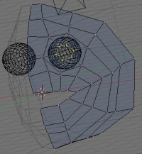
- Move the vertices surrounding the eye into more of a circular shape as in Forming the eye 1.
- Select the eye socket with AltRMB
 and scale it up a little with S as in Forming the eye 2.
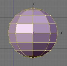
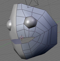
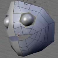
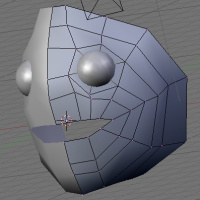
 - With the eye socket still selected, extrude it and scale it down (E>>Edges Only, S). Scale it down far enough that it goes into the eye. There shouldn't be any visible holes now, as in Forming the eye 3.
The ring that you just scaled down isn't visible. How to see it?
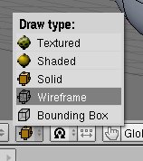
- Press Z to enter Wireframe mode (Eye socket in wireframe mode). Pressing Z again will get you back to Solid mode. Alternatively, select the Wireframe option from the Viewport Shading menu at the bottom of the 3D Window.
OR . . .
- . . . Press the "Limit selection to visible" button at the bottom of the 3D Window. This button is only available in Edit Mode & will not be visible if the current Viewport Shading mode is set to Wireframe.
Viewport Shading
Z to switch between Solid and Wireframe draw modes.
Or use the Viewport Shading menu to switch draw modes.
Press the "Limit selection to visible" button to toggle the visibility of vertices behind faces.
More info: Manual/PartII/Draw types
Up until now, we've been using the default Solid draw mode. That's when you see the solid faces of the mesh. By default, vertices that are behind the visible faces are invisible and you can't select them. This makes the interface faster (less vertices to calculate) and keeps the view uncluttered. Often, however, we need to see inside of a mesh. That's when you use either Wireframe draw mode or toggle Back-Face Visibility.
OK, now for a little more shaping to make some eyelids.
- Loop-cut the ring around the eye socket (CtrlR) to get some more vertices to work with (Loop cutting the eye socket).
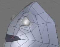
- Pull those new vertices forward and down a little using G to start forming the eyelid, as in Forming the eyelid 1.
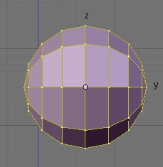
- Make another loop cut (CtrlR between the old and new rings to get even more vertices, and move them around to give the eyelid some more body. To do this, pull the top vertices up a little bit, and the bottom vertices down a little bit, something like Forming the eyelid 2.
Why don't we want too many vertices?
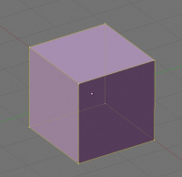
Throughout this tutorial I talk about adding only as many vertices as we need. Generally speaking we want to have only enough vertices as we need to get the shape we're modeling. For example, we only need 8 vertices to model a cube . . . any more vertices are unnecessary.
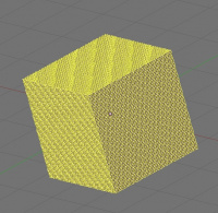
You might think that more vertices are bad because it will slow down your computer. Typcially, this is not the case. For example, I had to subdivide the cube several times to get a vertex count of almost 25,000 vertices before I saw noticable slowdown on my computer when I rotated the view. We'd be hard-pressed to make a single character with that many vertices.
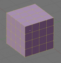
So if computing power is not limiting, what is? Brain power. When you're modeling, you generally have to select individual vertices and move them into place. The more vertices, the more selecting and moving you have to do. Imagine trying to make the cube into a truncated pyramid by scaling down the top. It's simple to do with an 8-vertex cube, but it would take more time to select the vertices with the 98-vertex cube or the 24,578-vertex cube. So it's a matter of convenience.
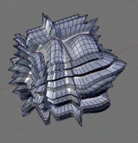
The more complex the shape, however, the more vertices are needed. For example, the object to the right needs just about all 1,538 vertices to make the shape.
In the end, it's up to you. These are just general guidelines. The point is, you don't have to go out of your way to reduce the number of vertices in your mesh to the absolute minimum. If you think you need extra vertices, add them!
Don't forget to save a version with F2-+ NumPad-↵ Enter!
Summary
We extruded the mouth further to form the face, added an eye, then duplicated and mirrored the eye using the 3D Cursor as a reference point. After a few more tweaks to the mesh, we now have a face with eyes and eyelids.
Now we can finish making the head.
|
Next: Finishing the head
Previous: Creating the mouth
