「Doc:2.6/Tutorials/Your First Animation/2.Animation」の版間の差分
細 (1版 をインポートしました) |
|
(相違点なし)
| |
2018年6月29日 (金) 04:41時点における最新版
目次
Your First Animation in 30 plus 30 Minutes Part IІ
If all we needed was a still picture, our work would be done, but we want Gus to move. The next step is creating a skeleton or armature, which will allow us to move him. This is called rigging. Gus will have very simple rig: four limbs (two hands and two legs) and several joints (no elbows, only knees), no feet and no arms.
Rigging
To add rigging:
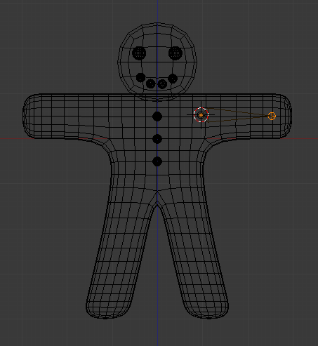
- In Object mode, set your 3D cursor where Gus’s shoulder is, and press ⇧ ShiftA >> Add >> Armature >> Single bone. A rhomboidal object will appear, which is a bone of the armature system. Enter Edit mode. The end, or tip, of the bone is selected (yellow).
- Now in Edit mode, place the tip of the bone in Gus’s hand by grabbing (G) and moving it, (Adding the first bone, an elbowless arm). We don’t need any other bones right now. You should now have one bone running from the shoulder to the hand area. As you move the tip, you will notice that the whole bone gets bigger – you really are scaling up the bone.
To make the process more successful, please periodically look at the Gingerbread man and armature from many different viewpoints to make sure the armature is inside the gingerbread man, just as bones are inside a human body. Skinning will fail if the bones are for example in front or in back of the body. Inspection from many different viewpoints is a common 3D model creation technique.
About Bones’ Ends
Bones’ ends can have different names. In Blender, currently they are called “head”/“tail” (the first being the “large” end, and the second the “thin” end). However, historically, they have been named “root”/“tip”, which is often considered somewhat less confusing…
|
- Stay in Edit mode, then move the cursor to where the hip joint will be and add a new bone ⇧ ShiftA.
- Grab (G) and move the yellow tip of the new bone to the knee area.
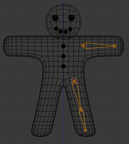
- Now “chain” a new bone from the knee to the foot by CtrlLMB
 clicking in the area of the foot. A new chained bone will appear automatically linked with the knee and ending at the foot, (Adding the second and third bones, a leg bone chain). Another way of chaining the new bone would be to extrude using the E shortcut. This variation creates the new bone and places you in grab mode automatically. Click LMB
  to validate the current bone’s tip position.
Bone position
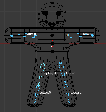
The bones we are adding will deform Gus’s body mesh. To produce a neat result, try to place the bone joints as shown in the illustrations.
|
Bone roll
To get the bones lined up as in (Adding the second and third bones, a leg bone chain) you may need to adjust the Bone Roll by pressing CtrlN, 3 with the lower leg bone selected.
|
We now have three bones that make up Gus’s armature.
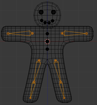
- Now place the cursor in the center (⇧ ShiftC) and select all bones with A. Duplicate them with ⇧ ShiftD and immediately exit grab mode with Esc. Make sure the cursor is selected as the rotation/scaling pivot (Pivot drop-down list in the 3D window header). Flip the duplicated bones along the X axis relative to the cursor with CtrlM and then X. Click LMB
 to confirm the mirror operation. You end up with (The complete armature after duplicating and flipping).
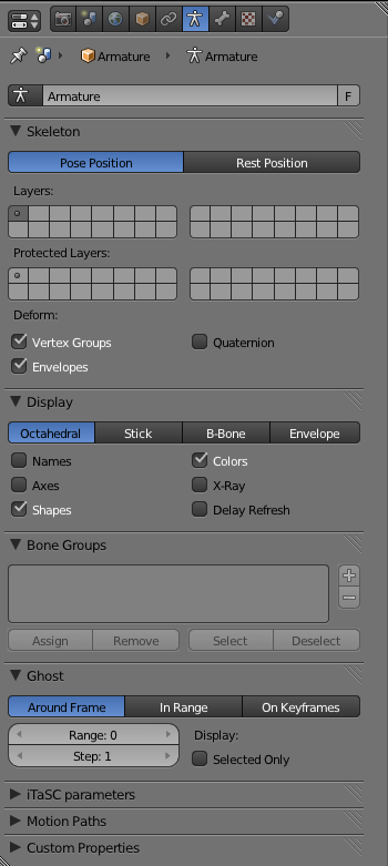
When any bone is selected the Object Data context shows settings for the Armature as a whole, such as the name of the Armature Object and settings for displaying the armature, while the Bone context shows the name of the active Bone and bone specific settings.
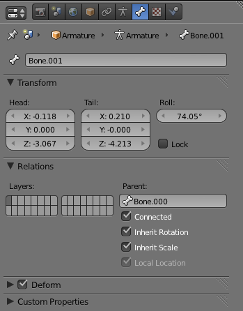
Check the Names checkbox (Armature context, Display panel) to see the names of the bones in 3D views, then select each bone and LMB ![]() click on the name of the bone in the Bones context to change the bone names to something appropriate like
click on the name of the bone in the Bones context to change the bone names to something appropriate like Arm.R, Arm.L, UpLeg.R, LoLeg.R, UpLeg.L and LoLeg.L, see (Armature Bones context). Exit Edit mode with ⇆ Tab.
Naming Bones
It is very important to name your bones with a trailing “
.L” or “.R” to distinguish between left and right ones, so that the Action Editor will be able to automatically flip your poses. |
Skinning
Now we must make it such that a deformation in the armature causes a matching deformation in the body. We do this with skinning, which assigns vertices to bones so that the formers are subject to the latter’s movements.
- In Object mode, select Gus’s body, then ⇧ Shift select the armature so that the body is dark orange and the armature is light orange.
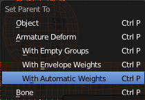
- Now we need to parent the body to the armature. That is achieved by pressing CtrlP). The (Parenting menu) will appear. Select the Armature Deform >> With Automatic Weights entry.
Vertex Groups, Envelopes and the order of modifiers
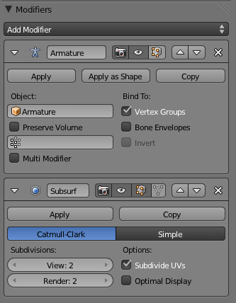
When skinning a mesh, the mesh object will get an Armature modifier attached to the bottom of its modifier stack. Gus' mesh already has a Subdivision Surface modifier on the stack. In order to get a smooth deformation of the mesh you should move the Armature modifier to a position above the Subdivision Surface modifier. You do this by clicking the Move Modifier buttons in the Modifier context (The modifier stack in the Modifiers context).
Also, each bone has an area of influence called Envelope. The armature will deform the mesh from both the assigned vertex groups and the bone envelopes. This may lead to unwanted results, so in our case it is important to disable Bone Envelopes in the Armature Modifier (The modifier stack in the Modifiers context).
|
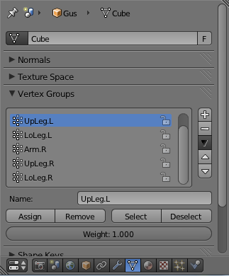
- Now select just Gus’s body and switch to Edit mode (⇆ Tab). Notice in the Object Data context the presence of the Vertex Groups group of controls in the Vertex Groups panel (The vertex groups controls in the Object Data context).
By scrolling in the Vertex Group panel, you can see all available vertex groups – six in our case. But a truly complex character, with hands and feet completely rigged, will have tens of them! See (The vertex groups controls in the Object Data context). The buttons Select and Deselect (de)select all vertices of the current selected group, which allows you to see which vertices belong to which group.
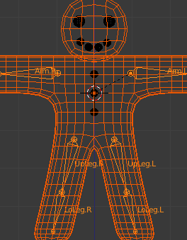
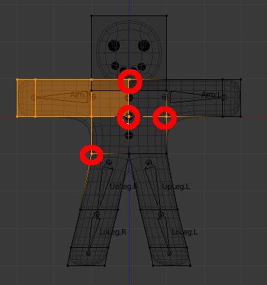
Select the right arm group (Arm.R) and, with all vertices deselected (A, if needed), press Select. You should see something like (Gus in Edit mode with all the vertices of group Arm.R selected).
If you don’t see the same thing then you probably placed the bones in just the right place such that the auto skinning process did a better job of matching vertices with bones. It is highly unlikely that the skinning process matched the vertices to the bones as exactly as you may expect. This requires that you begin to manually adjust the grouping as described in the following sections.
The vertices marked with red circles in (Gus in Edit mode with all the vertices of group Arm.R selected) belong to the deformation group, however, they should not.
The auto skinning process found that they were very close to the bone so it added them to the deformation group. We don’t want them in this group since some are on the opposite side of Gus and some are in the chest, adding them to the deformation group would deform those body parts as well.
To remove them from the group, deselect all the other vertices, those which should remain in the group, using box selection (B), but with MMB ![]() , not LMB
, not LMB ![]() , to define the box, so that all vertices within the box become deselected.
, to define the box, so that all vertices within the box become deselected.
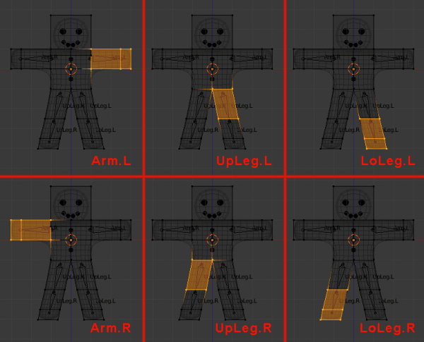
Once only the “undesired” vertices are selected, press the Remove button (The vertex groups controls in the Object Data context), to eliminate them from the group Arm.R. Deselect all (A) then check another group. Check them all and be sure that they look like those in (The six vertex groups).
Vertex groups
Be very careful when assigning or removing vertices from vertex groups. If later on you see unexpected deformations, you might have forgotten some vertices, or placed too many in the group. You can modify your vertex groups at any time.
Other details
Our deformations will affect only Gus’s body, not his eyes, mouth, or buttons, which are separate objects. While this is not an issue to consider in this simple animation, it’s one that must be taken into account for more complex projects, for example by parenting (to vertices) or otherwise joining the various parts to the body to make a single mesh (all these options are detailed in the manual).
|
Posing
Once you have a rigged and skinned Gus you can start playing with him as if he were a doll, moving his bones and viewing the results.
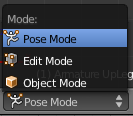
- Select the armature only, then select Pose Mode from the Mode menu (Mode menu in the 3D window header) – or simply hit Ctrl⇆ Tab. This option is only available when an armature is selected.
- The selected bones in the armature will turn blue. You are now in Pose mode. If you now select a bone, and you move it (G), or rotate it (R), the body will deform accordingly!
Original position
Blender remembers the original position of the bones. You can set your armature back by pressing AltR to clear the bones’ rotation, and AltG to clear their location. Alternatively, the Rest Position button in the Object Data context may be used to temporarily show the original position.
Inverse Kinematics
Inverse Kinematics (IK) is where you actually define the position of the last bone in the chain, often called an “end effector”. All the other bones assume an algorithmic position, automatically computed by the IK solver, to keep the chain without gaps (i.e. IK will mathematically solve the chain positions for us). This allows a much easier and precise positioning of hands and feet using IK.
Forward Kinematics
While handling bones in Pose mode, notice that they act as rigid, inextensible bodies with spherical joints at the end. You can grab only the first bone of a chain and all the others will follow it. All subsequent bones in the chain cannot be grabbed and moved, you can only rotate them, so that the selected bone rotates with respect to the previous bone in the chain while all the subsequent bones of the chain follow its rotation.
This procedure, called Forward Kinematics (FK), is easy to follow but it makes precise location of the last bone in the chain difficult.
We’ll make Gus walk, using FK, by defining four different poses relative to four different stages of a stride. Blender will do the work of creating a fluid animation.
- First, verify that you are at frame 1 of the timeline. The frame number appears in a numeric field in the Timeline window header (The current frame numeric field in the Timeline window header). If it is not set to 1, set it to 1 now.
- Now, by rotating only one bone at a time (R), we’ll raise
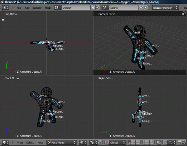
UpLeg.Land bendLoLeg.Lbackwards while raisingArm.Ra little and loweringArm.La little, as shown in (Our first pose).
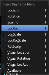
- Select all bones with A. With the mouse pointer on the 3D window, press I. A menu pops up (Storing the pose to the frame). Select LocRot from this menu. This will get the position and orientation of all bones and store them as a pose at frame 1. This pose represents Gus in the middle of his stride, while moving his left leg forward and above the ground.
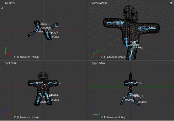
- Now move to frame 11 either by entering the number in the numeric field or by pressing ↑. Then move Gus to a different position, like (Our second pose). Start with clearing the rotation on both arms using AltR as mentioned earlier. From the top view, rotate
Arm.Rslightly forward andArm.Lslightly back. Finish the pose with his left leg forward and right leg backward, both slightly bent. Gus is walking in place!
- Select all bones again and press I to store this pose at frame 11, and select Rot.
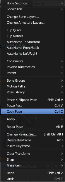
- We now need a third pose at frame 21, with the right leg up, because we are in the middle of the other half of the stride. This pose is the mirror of the one we defined at frame 1. Therefore, return to frame 1 and, with all the bones selected, in the Pose menu of the 3D window header, select the Copy Pose entry, see (Pose menu). Or use CtrlC. You have now copied the current pose to the buffer.
- Go to frame 21 and paste the pose with the Paste X-Flipped Pose option in the Pose menu, see (Pose menu). Or use ⇧ ShiftCtrlV. This will paste the cut pose, exchanging the positions of bones with suffix “
.L” with those of bones with suffix “.R”, effectively flipping it!
Bone roll
If pasting an X-flipped pose makes Gus bend in the wrong direction you may have some trouble with the Bone Roll. Select all bones in Edit Mode and press CtrlN, 3 to sort out the bone roll. Then go back to frame 1 and 11 and adjust the poses. Re-copy the pose from frame 1 and again try pasting the x-flipped pose in frame 21.
|
The pose is there but it has not been stored yet! You must press I » Rot with all bones selected.
- Now apply the same procedure to copy the pose at frame 11 to frame 31, also flipping it.
- To complete the cycle, we need to copy the pose at frame 1, without flipping it, to frame 41. Do so by copying it as usual, and by using the Paste Pose entry. Or use CtrlV. End the sequence by storing the pose with I » Rot.
Checking the animation
To preview your animation, set the current frame to 1 and press AltA in the 3D window.
|
Gus walks!
The single step in-place is the core of a walk, and once you have defined one there are techniques to make a character walk along a complex path. But, for the purpose of our Quick Start, this single step in-place is enough.
- In the Render context in the Properties window, set the start frame (Start) to 1 (it should already be at 1 by default) and set the end frame (End) to 40 (it is set to 250 by default, see Settings for an animation in the Render context). Because frame 41 is identical to frame 1, we only need to render frames from 1 to 40 to produce the full cycle.
- Type //render/ in the text field in the Output panel.
- Select AVI Raw as the file type in the Format panel. While this is generally not the best choice, mainly for file size issues, it is fast and it will run on any machine, so it suits our needs. You could also select AVI Jpeg to produce a more compact file. However, it uses lossy JPEG compression and will produce a movie that some external players might not be able to play.
Finally, press the Animation button in the Render panel. Remember that all the layers that you want to use in the animation must be shown! In our case, these are layers 1 and 10.
Stopping a Rendering
If you make a mistake, like forgetting to turn layer 10 on, you can stop the rendering process with Esc.
|
Our scene is pretty simple, and Blender will probably render each of the forty images in a few seconds. Watch them as they appear.
Stills
Of course you can always render each of your animation frames as a still by selecting the frame you wish to render and pressing the RENDER button.
|
Once the rendering is complete you should have a file named 0001_0040.avi in a render subdirectory of your current directory – the one containing your .blend file. The directory can be changed from the Output panel.
You can play this file directly within Blender by pressing Play Rendered Animation in the top menu (or by using CtrlF11). The animation will automatically cycle. To stop it press Esc. We have produced only a very basic walk cycle. There is much more in Blender, as you’ll soon discover reading its whole manual!
