「Extensions:Uni-Verse/BlenderVsVerse」の版間の差分
細 (Bot: Fixing redirects) |
細 (1版 をインポートしました) |
(相違点なし)
| |
2018年6月29日 (金) 02:50時点における最新版
目次
Introduction
This little article talks about the differences known between low-level geometry representations between Blender and Verse.
I (Emil Brink) mainly wrote it since I spent a lot of time on the subject, trying to figure out why I had been seeing some odd results in Blender when interacting with a Verse server holding a moderately complex scene, and I wanted to summarize the results somewhere. Perhaps they can be useful to someone.
The basic reason why this stuff needs to work is to promote interoperability. It would probably be possible to treat Verse as a stupid storage back-end for Blender, and cram Blender data into whatever Verse data container is suitable, without caring for the (somewhat subtle) differences in interpretation of these values that exist between the two. Doing so, however, would not be a good use of Verse.
Verse is about interoperating, and sharing data with other programs, tools, and people. Assuming the other end of the Verse server is running the same application as any one user ("the world is Blender"-thinking), is not a recommendable way of thinking about Verse. So don't do that, okay? Thanks. :)
Different Coordinate Systems
Blender and Verse have different "native" coordinate systems. It might perhaps be argued from a purely theoretical standpoint that they are the same (both are right-handed cartesian systems with orthogonal base axis called X, Y and Z), but for practical purposes, they differ since they are interpreted differently.
The differences are hopefully made clear below:
Blender's Coordinates
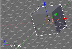
Here is a cropped screenshot from Blender, showing a cube and two sets of red/green/blue coordinate axis:
As you can see, the orientation is like this:
- The X (red) axis points to the right.
- The Y (green) axis points "into" the screen.
- The Z (blue) axis points up.
This means that if there was a "ground" in Blender, that models were to be placed upon, it will be occupying the XY plane.
Verse's Coordinates
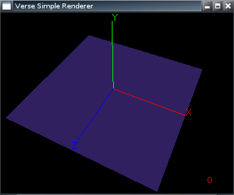
Here is an equivalent image from a Verse application (the Simple Renderer), showing a similar set of coordinate axis, using the same color coding convention (red for X, green for Y, blue for Z):
The blue plane shows how the "ground" is oriented in Verse; it is in the XZ plane, with positive Y pointing up. This leaves positive Z pointing out of the screen, while positive X is to the right, just as in Blender.
Geometry Representations
Vertex Data
Let us start by looking at vertex coordinates, and how they need to be transformed when going from Verse to Blender (downloading geometry from a server) and vice versa (uploading edits to the server).
Initially, it might not be obvious that anything needs to be done. The coordinate systems are very compatible-looking, but seem to be a bit differently oriented, but so what?
Well, it becomes very confusing to use Blender to edit a Verse scene if the orientation of each mesh changes totally during the download. Thus, it is highly desirable for Blender to swap around the coordinates so that a mesh ends up oriented properly in Blender, even though Blender uses the axis differently.
To figure out the required transform, let's just look at an incoming vertex, axis by axis, in the Verse coordinate system image, and find out the corresponding location in Blender's space:
- X is the easiest, since X is oriented the same way for both. Nothing needs to be done for X.
- An incoming vertex with a large Y value needs to end up "high" in Blender. The way to do this seems to be to assign it a large Z value. So, we set Blender's Z to Verse's Y.
- A Verse vertex with a large Z value needs to be "close" to the viewer. This seems to be along the negative Y axis in Blender, so we set Blender's Y to the negation of Verse's Z.
This ends up with a transform that can be written in C like so:
 struct Point {
   double x, y, z;
 };

 struct Point verse_to_blender(Point v) {
   struct Point b = { v.x, -v.z, v.y };
   return b;
 }
The above code is probably not the most efficient way of doing the transform (one function call per vertex), but it shows the theory clearly, I hope. Taking the above points backwards, we can reason our way to the inverse transform, for sending a Blender vertex back to Verse:
 struct Point blender_to_verse(Point b) {
   struct Point v = { b.x, b.z, -b.y };
   return v;
 }
Let's test the above transforms on a couple of sample points, to see that they indeed do the right thing:
| Incoming Verse Vertex (v1) | b = verse_to_blender(v1) | v2 = blender_to_verse(b) |
|---|---|---|
| (0,0,0) | (0,0,0) | (0,0,0) |
| (1,0,0) | (1,0,0) | (1,0,0) |
| (1,2,3) | (1,-3,2) | (1,2,3) |
| (-3,10,0) | (-3,0,10) | (-3,10,0) |
It should be clear that for all incoming vertices v1, the chain of transforms v2 = blender_to_verse(verse_to_blender(v1)) results in v2 being equal to v1.
Meshes
One important thing about Verse is that there is only one geometry primitive: the creased subdivision surface. This means any other primitive must be translated into the form of a subdivision surface, in order to be representable in Verse.
As a special case, a Verse surface that has all vertices and edges marked as "sharply creased", is identical to a basic mesh model.
Further, Verse supports only triangles and quads in forming the control meshes for the subdivision surfaces. Quads are by far the more efficient of the two, and is recommended whenever possible.
Note that "mesh" is not a term used in Verse. Verse geometry storage (through the Geometry node) deals with vertices and polygons.
Object Representations
This section discusses differences in how objects are represented, with a focus on concrete things such as positioning. Objects are assumed to be the top-level, individual, entities in a scene. Objects may share geometry.
Translation
Translation, i.e. the positioning of an object, must be done while taking the differences of coordinate system interpretations into account. A Verse object with a translation equal to (0,1000,0) tries to be above an object at (0,0,0), and that needs to be visible in Blender too.
The transforms given above should work for object translations, too.
Scaling
Just as with translation, scaling needs to be axis-swapped. Again, the same transform functions should work for this task too.
Rotation
Verse uses quaternions to represent rotations. Blender seems to use Euler angles most of the time, but has code to translate to/from quaternions when required.
Much can be said about quaternions and their application for expressing rotations, but since I'm not an expert in the field, I won't attempt to cover it like one. One good primer is this page, especially the nice section that has some literal quaternions together with explanations of the rotations they represent. The linked-to page is about the Ogre 3D engine; it might be helpful to know that Ogre uses the same coordinate system as Verse does (see here for their explanation).
Quaternions in Blender are (regrettably, in my humble opinion) not given a representation as a type, they are instead just handled as short arrays of floats. This means it's not clear which field in the quaternion is where, and it is not possible (as far as I know) to refer to the fields by name, only by numerical index into the array.
Quaternions in Verse are represented using the two typedef:ed structures VNQuat32 and VNQuat64. These have the exact same fields, the only difference is that the former uses real32 (typically an alias for float, i.e. a 32-bit floating point value) for its fields, while the latter uses real64 (again, typically an alias for double, a 64-bit floating point value). The fields of the quaternion are named x, y, z and w, and they occur in that order in the structure. The order does of course not matter, as long as the fields are referenced by name and not through sneaky pointer-trickery.
The differences in coordinate system rear their not-too-attractive head once again here, perhaps in the most complicated way so far. I am not yet fully convinced I know how to deal with the differences, so I can't be very conclusive here. :/ Here are a few ideas, though:
- The identity quaternion seems to be represented as [1 0 0 0] in Blender, since Blender stores its quaternions in [w x y z] order in the arrays. In Verse, the identity would look as [0 0 0 1] if viewed as an array, since the order of the fields in the VNQuatn structures is x y z w. This is something to keep in mind when translating.
- The differences between Blender's and Verse's coordinate systems can be summarized as "To go from Verse to Blender, rotate 90 degrees clock-wise around the X axis". Perhaps this means that rotations can be translated by multiplying the Blender internal quaternion with a -90 degree rotation around X, and sending the result to Verse? I have not tested this, since the integration of rotation handling is still a bit over my head.
Material Representations
The differences in how Blender (and quite a few other 3D applications) deal with object materials, and how Verse does it, are probably a bit too large to be covered in this document.
Basically, Verse does not have a fixed-function material system, with a set number of options you can tweak. Instead, Verse uses a sort of graphical programming language to express how to compute for instance the color of each pixel of a surface. The language has 16 primitives, that can be combined to achieve many different effects. I think this is similiar to the new nodes system in Blender, too, although Verse very probably has far fewer nodes.
As a simple example, this howto shows how to implement texture-mapping on a surface using Verse's material system.

