利用者:Sobotka/Color Management/Calibration and Profiling
目次
- 1 Calibration and Profiling in an OpenColorIO Based Pipeline
- 2 Intended Audience and Aptitude
- 3 Calibration and Profiling are Different!
- 4 Q: What do I need to calibrate and profile a monitor?
- 5 Q: What is a calibrated and profiled monitor?
- 6 Q: What software tools will we need to accomplish this?
- 7 Q: Are there a minimal number of things I need to do to achieve a calibrated and profiled display?
- 8 Using DispcalGUI
- 8.1 Select Your Hardware Color Device
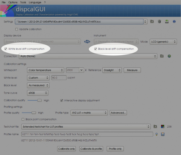
- 8.2 Enable White Drift and Black Drift Compensation
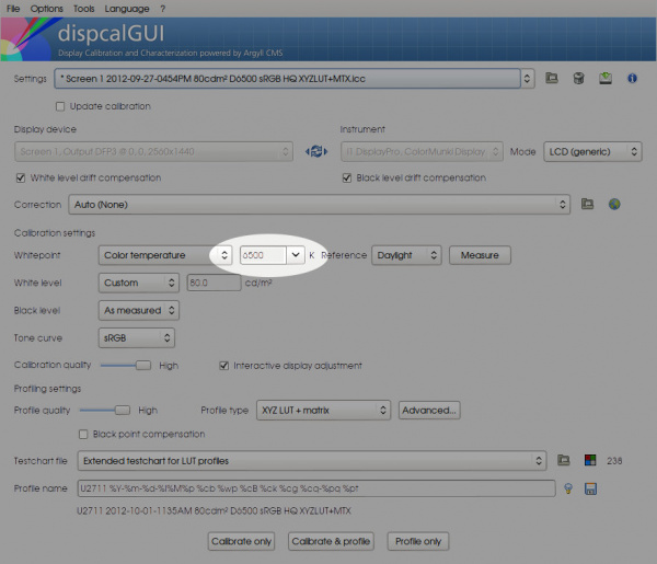
- 8.3 Choose the Target sRGB IEC61966-2.1 Specified White Point
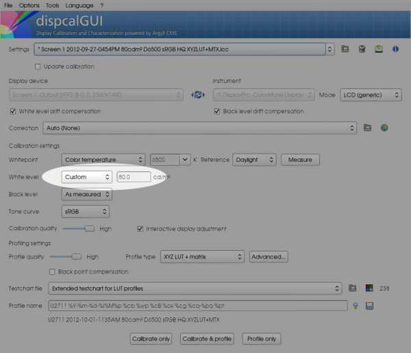
- 8.4 Choose the Target sRGB IEC61966-2.1 Specified White Level
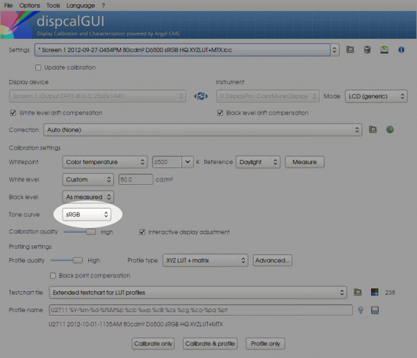
- 8.5 Choose the Target sRGB IEC61966-2.1 Specified Transfer Curve
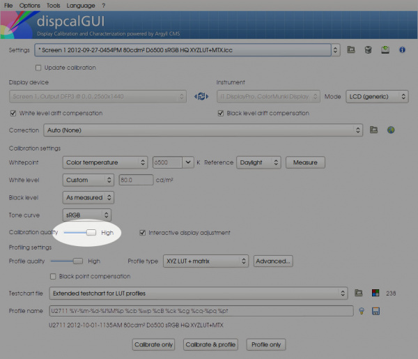
- 8.6 Choose High Calibration Quality
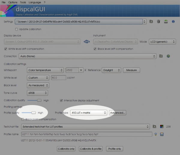
- 8.7 Choose XYZ LUT and Matrix and High Profile Quality
- 8.8 Deselect Black Point Compensation
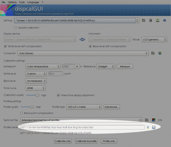
- 8.9 Assert File Name is Meaningful
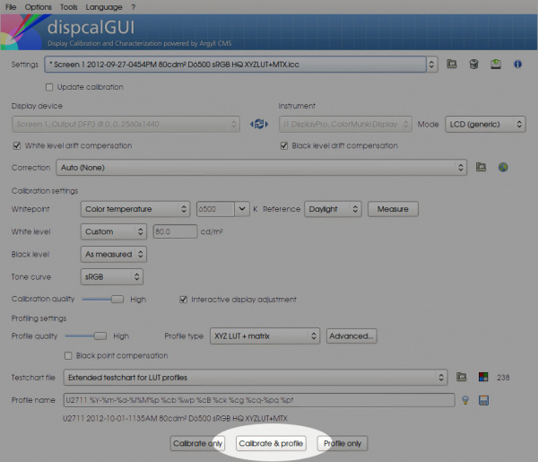
- 8.10 Begin Calibration and Profiling
- 8.11 OPTIONAL: Attempt to Match Calibration Targets
- 8.12 Proceed to Profiling
- 8.13 Create a 3D Display Profile LUT
- 9 Testing the New Profile
- 10 Hook the 3D LUT into Blender
- 11 The Final Testing
- 12 Further Questions
- 13 Further Reading
Calibration and Profiling in an OpenColorIO Based Pipeline
This overview will walk a typical Blender artist across a few of the necessary details required to get a display device to a reference standard.
While this document is at a 1.0 version, there may be errors, omissions, and inaccuracies. Please utilize the Discussion page.
Intended Audience and Aptitude
The intended audience for this tutorial is an artist familiar with Blender with a display measuring instrument. She is familiar with color management principles and operating system details.
While the following tutorial is detailed in the interest of clarity, it is reasonable to expect that an artist with patience will get to the other end of the tunnel without a large degree of duress.
Duration
This tutorial will cover a large breadth of topics. An artist should expect to spend 70-120 minutes to complete this overview.
|
Blender Version
OpenColorIO was integrated into Blender version 2.64. You will need either a trunk build or a minimum build from 2.64 to complete this outline.
|
Calibration and Profiling are Different!
It should be stated clearly that calibration and profiling are different techniques. When one speaks of a "calibrated" display, it is radically different than a "profiled" display. Both procedures offer different ends and serve different roles.
Q: What do I need to calibrate and profile a monitor?
- First and foremost, a grasp of color management is important. Some of the concepts on this page will be of use if you are unfamiliar with what color management is and why it is important.
- A hardware colorimeter or spectrophotometer. There is no getting around this as our vision systems are adaptive and we require hardware as a baseline to measure. Luckily, many devices can be had for a relatively small investment to a typical artist.
- Software. Software is required to analyze the hardware readings and create, adjust, and load the output of our efforts.
Q: What is a calibrated and profiled monitor?
It is quite common to hear the phrase "Is your monitor calibrated?" Sadly, this tends to describe some sort of mythical, almost magical state that a display device can be in. In practical terms, preparing a display for a color managed pipeline is divided into two steps: calibration and profiling.
Q: What is calibration?
Calibration is the first specific phase of the process. Calibration involves manually tweaking the display itself to get it into a known state. During calibration, a monitor will have brightness, contrast, color, and other hardware based monitor controls adjusted. After calibration, a calibration file is created.
Q: What is loaded automatically? Where does this go?
During the calibration phase, the hardware controls on your display are tweaked to get it as close to a known target as possible. Within this testing, both color and transfer curve response is sampled. The sampled curve response is corrected as much as needed to match the curve response of the target, and the result is stored as data in a file somewhere on your computer. This file is traditionally loaded at boot time on a color managed system.
Q: Is calibration enough?
No. Calibration can only evaluate your display's transfer curve. The file that is loaded via the Video Card Gamma Tag (VCGT) is channel independent. That is, only the values of each channel can be adjusted independently.
As colors are mixes of channels, a loaded calibration file is unable to adjust the saturation intention of a given channel in relation to another channel. Those adjustments are in the domain of three dimensional LUT and matrix transforms, not one dimensional LUT transforms as the VCGT uses.
Q: Help! My head just poppped reading that!
If you don't quite yet understand what is going on at a low level with calibration, do not fret. The main take away point is that calibration is separate from profiling. The second take away point is that calibration cannot deliver accurate color unto itself.
Always remember the color management triangle at all steps in a pipeline.
Q: What is profiling?
During calibration, we generate a calibration file that is loaded into our video card that assures us that our transfer curve is uniform. After calibration, we use this known state to generate a profile. This involves using our hardware colorimeter to evaluate a series of known swatches to see how our display responds. The response is recorded into yet another file known as a profile. This profile provides the needed information for a color managed piece of software to reliably and accurately display output to our screen.
Q: Must I always calibrate prior to profiling?
Ultimately this depends on need. The short answer is no. A given monitor can be profiled and the responses can be used to transform between colors. As a general rule of thumb, calibrating to a known target and profiling against that target should result in a more accurate rendition. This may not always be the case and may not always meet the needs of a given pipeline.
The safest answer for those inexperienced with color management is to suggest to always calibrate and profile to known standards and utilize both in their pipeline.
Example
A pipeline might be utilizing a global wide gamut color space for all assets. In this instance, calibrating and profiling for a smaller gamut such as sRGB may result in gamut clipping when viewing on the pipeline monitors. Conversely, when displaying on typical sRGB displays, care must be taken to properly transform the wide gamut space down to the sRGB display space.
|
Q: What software tools will we need to accomplish this?
In order to calibrate and profile a display, we need software that can interact with our hardware display measurement device and create the needed output files. Thankfully, we have several extremely robust projects to help us along this complex path. They also happen to be open source and available to all with interest.
Q: Why do you suggest to pay attention to all of these details? I have a little application that came with my device and all I need to do is click it!
- Accuracy and assurance. Focusing on the color management triangle, we should realize that clicking a button is not equated with knowledge nor education. The chances that someone can click a button and end up with a color managed pipeline is about the same as someone half way around the world clicking a button and giving you that color managed pipeline. What is happening when you click that button?
- Fidelity of color space transforms. Gamut mapping relies on Color Appearance Models (CAM) that leverage complex algorithms to map a given color space / response to another. The further the distance of the gamuts, the less accurate the results. For example, Bradford, Von Kries, and XYZ scaling matrices will gradually degrade the gamuts proportionally to the distance of the white points. For further information, read Mark Fairchild's Color Appearance Models or read Bruce Lindbloom's excellent information on adaptation at his site.
- Consistency. Concurrent with the second point, gamut mapping can be the subject of proprietary and secret algorithms. This makes it extremely difficult to evaluate why outputs differ. All well known color spaces have specific targets for white point, primary chromaticities, and brightness, as well as parallel viewing conditions. This makes it extremely easy to communicate and evaluate color pipelines.
- Display fidelity. Concurrent with the second point, when a display is calibrated closely to a target gamut, it can often improve the fidelity of the display's ability to render that target.
The short answer is that, like any scientific experiment, the more constants we can control the greater chance for consistency.
Q: What is ArgylCMS?
ArgyllCMS is a command line driven set of tools that can be used to calibrate, profile, and achieve many other color management system needs. It includes a vast and powerful set of utilities that includes many advanced color management needs. ArgyllCMS's official website can be found at http://www.argyllcms.com/. A separate download and installation of Argyll is not required as it is included in the dispcalGUI package.
Q: What is dispcalGUI?
While ArgyllCMS is a command line driven utility set, dispcalGUI provides an extremely useful graphical user interface layer to the tool set. Based upon the work of Argyll, it evolves in tandem with it. The official website of dispcalGUI can be found at http://dispcalgui.hoech.net/.
Q: Are there a minimal number of things I need to do to achieve a calibrated and profiled display?
Calibrating and profiling a display can be achieved in a shorter period of time, hardware and settings notwithstanding. Performing the steps a few times will make the concepts become clearer to the artist. The following needs attempt to address the color management triangle assertions.
- Hardware: Purchase or borrow a colorimeter or spectrophotometer.
Colorimeters can be inexpensive and are easily found. Spectrophotometers tend to be more expensive. Be sure that your device is suitable for the gamut range of your display. For example, some colorimeters due to the filters on the sensors, are inappropriate for wide gamut displays. Also note that some vendors appear somewhat hostile to open source projects. - Software: Download and install dispcalGUI.
The official DispcalGUI site offers download links for most major platforms. If you wish to keep up with DispcalGUI development, there is source code made available publicly. The following outline assumes you have downloaded and installed DisplaycalGUI and it is in working order. - Awareness: Think about a target.
Perhaps the most overlooked and confusing aspect of color management is the notion of source and destination color space targets. If you have read over the basic color management page you will hopefully have an idea that color doesn't exist in some simplistic vacuum. You need to know what your target is and be aware as to what you are calibrating towards.
Jump to Further Questions if you have an interest as to why certain decisions are made in this document.
Using DispcalGUI
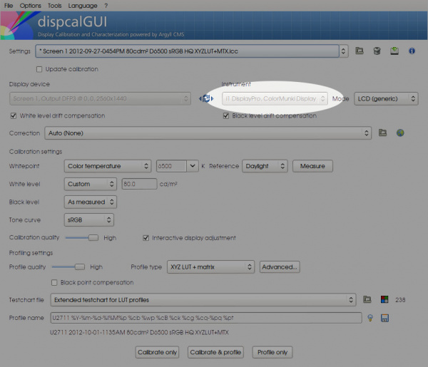
Select Your Hardware Color Device
Enable White Drift and Black Drift Compensation
Choose the Target sRGB IEC61966-2.1 Specified White Point
Choose the Target sRGB IEC61966-2.1 Specified White Level
Choose the Target sRGB IEC61966-2.1 Specified Transfer Curve
Choose High Calibration Quality
Choose XYZ LUT and Matrix and High Profile Quality
Deselect Black Point Compensation
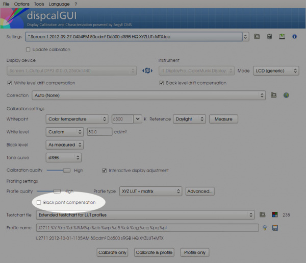
Assert File Name is Meaningful
Begin Calibration and Profiling
Lengthy Process
Calibration and profiling can be a lengthy process depending on hardware and software settings. Be forewarned, this may take some time.
|
Display Illumination
Display illumination is electronic and as such takes time to warm up to optimal levels. Only calibrate and profile a display that has been turned on for longer than thirty minutes.
|
CRTs and LCDs
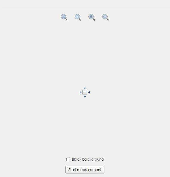
CRTs behave differently than LCDs on a number of levels. In particular, when calibrating and profiling on a CRT display, the nature of the cathode ray scan line will be impacted by surrounding graphical elements. It may be necessary to perform the measurements with the black background option set to on. This is not necessary for LCD measurement.
|
OPTIONAL: Attempt to Match Calibration Targets
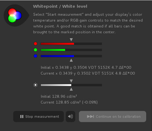
Contrast and brightness will constantly interact with RGB levels. This can be a tricky balancing process.
- Brightness adds or subtracts an overall offset to your RGB channels. This means that the white and black level will be adjusted upwards or downwards overall. Think of brightness as moving both the white and black points in unison via an offset. As the white gets lighter, the black does as well.
- Contrast scales the RGB channels overall. Adjusting contrast over brightness will likely result in the least impact of your overall black level. For further reading on contrast and brightness see Charles Poynton's canonical reference. Think of contrast as brightening the display by stretching the distance between white and black. As the white gets lighter, the black is distanced from it.
- More industrial grade displays will offer more granularity and additional controls including gamma and other adjustments. In addition to this, often multiple user controlled configuration slots are provided for a range of user based configurations.
The goal of this process is to get as close to the target white point and overall white level target as possible. It is a tricky balancing act!
- The RGB meter bars are ratios, and keeping them as close together as possible is desirable. If the Blue meter bar, for example, is far to the right, try bringing it into the range of the Red and Green channels. Also note how this will impact your overall proximity to the target brightness and adjust the contrast and brightness accordingly.
- Once more or less uniform, adjust the contrast to bring the lower overall white level bar close to the target. If smaller increments are required, often adjusting brightness one direction or another and compensating on contrast will help.
- Repeat until the output label changes to green indicating a close proximity to target.
Proceed to Profiling
Profiling will display a series of swatches on the screen. This will be automated and requires no interaction with the display. Simply wait while all swatches are measured. This may be for a long duration as it depends on the sensor sensitivity of your device and the overall swatch count. Make sure that your measurement device will be undisturbed and periodically check to make certain that a screen saver hasn't taken over the display.
Once finished, you can view your curves and gamut before saving the results.
Create a 3D Display Profile LUT
From the Tools menu, select "Create 3D LUT..."
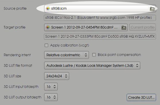
Choose the Source Space Profile
We have a profile that now attempts to meet the white point and overall white level of the sRGB space. We now need to create a transform that starts at a proper sRGB set of chromaticities and transforms into our display's profile characteristics.
Using the file browser locate where DisplaycalGUI is on your drive, and under the refs directory select the sRGB.icm file. This file matches the specification. There are an unfortunate number of sRGB profiles out in the wild, and not all are created equally, so caveat emptor.
This sRGB profile forms our new source color space. This LUT will be used when we seek to transform values from sRGB values to our display's profile.
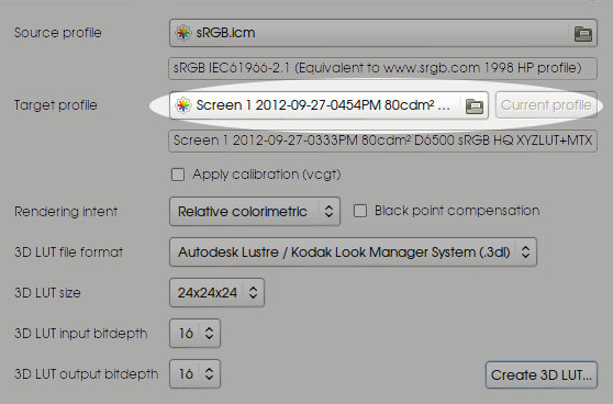
Choose the Target Space Profile
Our target is now our display's profile characteristics. In order for the software to calculate how this transform should occur, we must select our newly created display profile from the directory where it is stored.
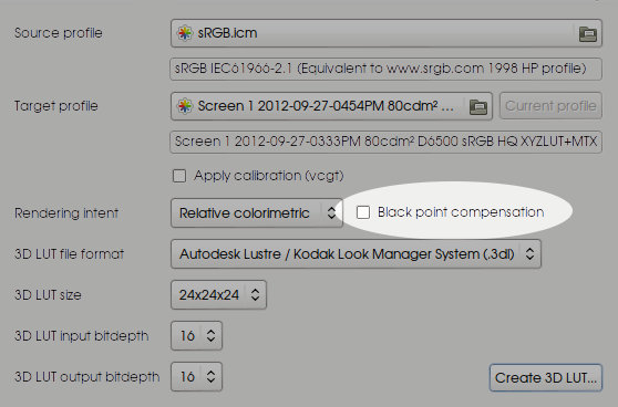
Turn Off Black Point Compensation
Again, to eliminate as many variables as possible, we will disable Black Point Compensation.
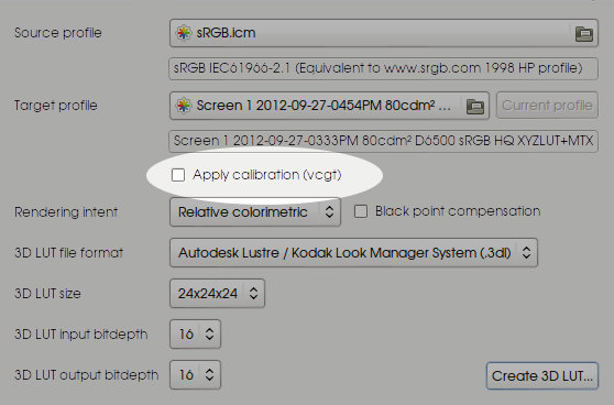
Turn Off VCGT Calibration Transform
Because we will already hopefully have the Video Card Gamma Table calibration loaded into our video card, we should also disable this option. If we fail to disable this, the VCGT transform will be baked into the LUT. When we use the resultant LUT on a system with OS level VCGT calibration loaded, the result would be a doubling up of the VCGT calibration.
Quality Settings
Select a 24x24x24 cube size and 16 bit depth as the final requirements. Feel free to experiment with these settings as you get more adept with color management.
Testing the New Profile
For the sake of this test, we will use an application such as Photoshop or GIMP. As this is not the focus of this tutorial, achieving this will not be outlined in depth. As a loose outline:
- Load the graphics application.
- Locate in preferences where color management is. Assert that color management is enabled.
- Set the working space to the sRGB.icm file we used to generate our 3D LUT. While this isn't required, we will use this setting to test our output from within Blender. The sRGB.icm profile can be left or an artist can choose alternate spaces after this tutorial is over.
- Set the display to the profile we created above.
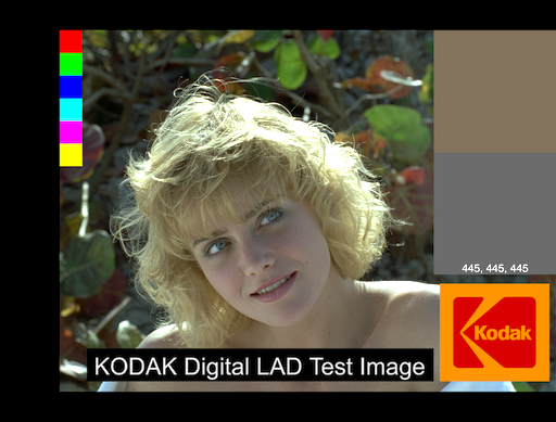
- View a test image. In the name of consistency, use the OpenColorIO reference images set from the downloads section. We will use the /nuke-default/marci_512_srgb.png image stored inside the archive.
The marci_512_srgb.png test image will likely look noticeably different under the properly color managed settings as compared to without. Everything from overall color and saturation to tonal curves will be subtly noticed. Toggle the color management on and off. Compare against an alternate image viewer and an unmanaged web browser to assert the results are as expected.
As can be expected, application software of all price ranges and quality can get color management pipelines subtly wrong. Everything from a doubling up on the VCGT transform to per-application settings might muddle the process. With experience and knowledge, an artist can detect these issues and convert them into meaningful solutions.
Hook the 3D LUT into Blender
The final step is to hook our newly created 3D LUT into Blender. This involves editing the default OpenColorIO configuration file and integrating our LUT into the system.
Rename the 3D Display Profile LUT
This will make it vastly easier to integrate into the Blender OpenColorIO configuration file. A simple shorthand name of display and a date should suffice. Keep the .3dl extension. From here forward, this file shall be referred to as <DISPLAY_LUT>.
Locate the OpenColorIO Configuration Directory for Blender
The default OpenColorIO Configuration file should be in the /bin/<VERSION>/datafiles/colormanagement directory. OpenColorIO was integrated into version 2.64, but your version may differ.
The default configuration file in OpenColorIO is labeled config.ocio. Blender also uses the default system OpenColorIO system environment variable OCIO. If you wish to use a custom path, you are free to do so merely by changing the system wide OCIO variable. An example for *nices might be:
export OCIO="/full/path/to/the/config.ocio"
If editing configuration files makes you worry, simply create a copy of the config.ocio and the luts directory and store it somewhere safe such as a backup directory in the datafiles directory.
Copy the <DISPLAY_LUT> to the "luts" Directory
In the OpenColorIO directory located above, there is a single directory called "luts". The full URI for a Blender build should be:
/path/to/blender/bin/<VERSION>/datafiles/colormanagement/luts
Where <VERSION> is your current Blender version.
Copy your renamed version of the display LUT to this directory.
Edit "config.ocio" to Integrate the Display LUT
The config.ocio file may appear entirely confusing at first. We will only be adjusting a few elements to have our display LUT integrated into Blender.
Add the Display 3D LUT as a ColorSpace
Open up the config.ocio file in a text editor. Scroll to the bottom. Add a custom color space following this example:
[...]
  - !<ColorSpace>
    name: Non-Color
    family: raw
    description: |
        Color space used for images which contains non-color data (i,e, normal maps)
    equalitygroup:
    bitdepth: 32f
    isdata: true
    allocation: uniform
    allocationvars: [0, 1]

  - !<ColorSpace>
    name: p3dci8
    family: display
    equalitygroup:
    bitdepth: 8ui
    description: |
      p3dci8 :rgb display space for gamma 2.6 P3 projection.
    isdata: false
    allocation: uniform
    from_reference: !<GroupTransform>
      children:
        - !<ColorSpaceTransform> {src: Linear, dst: lg10}
        - !<FileTransform> {src: colorworks_filmlg_to_p3.3dl, interpolation: linear}
[...]
  - !<ColorSpace>
    name: p3dci8
    family: display
    equalitygroup:
    bitdepth: 8ui
    description: |
      p3dci8 :rgb display space for gamma 2.6 P3 projection.
    isdata: false
    allocation: uniform
    from_reference: !<GroupTransform>
      children:
        - !<ColorSpaceTransform> {src: Linear, dst: lg10}
        - !<FileTransform> {src: colorworks_filmlg_to_p3.3dl, interpolation: linear}

##########################################################
# This is where we will add our own color space transform.
##########################################################

  - !<ColorSpace>
    name: MyProfile
    family:
    equalitygroup:
    bitdepth: 32f
    description: |
      My display profile LUT.
    isdata: false
    allocation: uniform
    from_reference: !<GroupTransform>
      children:
        - !<FileTransform> {src: srgb.spi1d, interpolation: linear, direction: inverse}
        - !<FileTransform> {src: <DISPLAY_LUT>, interpolation: best}
Here we have added a color space to the OpenColorIO system. In particular, this is a GroupTransform, which is instructing the library that we want to do multiple transformations on the data. The transformations are as follows:
- The standard sRGB transfer curve. This is provided by an existing LUT in the directory. We only need to tell it to perform it in the inverse direction as we are coming out of the system, as indicated via the from_reference heading.
- Our actual display LUT, as loaded via an OpenColorIO FileTransform.
Keep the file open and proceed to the next step.
Add the New Color Space Transform to the Display Spaces
Finally, we make the newly created color space transform available as a display transform. Scroll up to the top of the file and add it in the following fashion:
[...]

  # Color spaces for color picking and exture painting (not internally supported yet)
  color_picking: Raw
  texture_paint: Raw

displays:
  sRGB:
    - !<View> {name: Default, colorspace: sRGB}
    - !<View> {name: RRT, colorspace: rrt_srgb}
    - !<View> {name: Film, colorspace: srgb8}
    - !<View> {name: Raw, colorspace: Raw}
    - !<View> {name: Log, colorspace: lg10}
    # Our newly created color space transform
    - !<View> {name: Profiled, colorspace: MyProfile}
  DCI-P3:
    - !<View> {name: RRT, colorspace: rrt_p3dci}
    - !<View> {name: Film, colorspace: p3dci8}
    - !<View> {name: Raw, colorspace: Raw}
    - !<View> {name: Log, colorspace: adx10}
  Rec709:
    - !<View> {name: Default, colorspace: nuke_rec709}
    - !<View> {name: RRT, colorspace: rrt_rec709}
  XYZ:
    - !<View> {name: Default, colorspace: XYZ}
    - !<View> {name: RRT, colorspace: rrt_xyz}
    - !<View> {name: DCI, colorspace: dci_xyz}
    - !<View> {name: Raw, colorspace: Raw}
    - !<View> {name: Log, colorspace: adx10}
  None:
    - !<View> {name: Default, colorspace: Raw}

active_displays: [sRGB, DCIP3, Rec709, XYZ, None]
active_views: [Default, RRT, Raw, Log]
[...]
Save the file and exit the text editor.
The Final Testing
If all has gone well, we have gone from an uncalibrated and unprofiled display to a calibrated and profiled display with a generated 3D LUT for sRGB usage.
The final test will be against the Marci test file above.
- Load Blender.
- Open a UV Image panel.
- Load the marci_512_srgb.png from above.
- Open up the Properties panel via the View menu or press n.
- In the left hand region, assert that the color space is set to sRGB for Marci. Enable the View as Render toggle to ensure the transform to display.
- In the Scene tab in the Properties panel, locate the Color Management panel at the bottom. You should now be able to toggle between Default and Profiled and see the sRGB image as it was intended.
Compare the results against the alternate applications as we did above.
Further Questions
Q: Why do I need a target?
In theory, a fully color managed pipeline can deal with any known calibrated / profiled combination with greater or lesser accuracy.
However, in many instances, especially when dealing with LUTs and lower level color issues, it is prudent to be aware of what color space and white point your given devices are calibrated and profiled to. Again, being aware of these factors helps to elevate an artist's knowledge of color management, enabling faster diagnostics and testing.
Q: What target color space should I choose?
For this exercise, we target the sRGB color space. The specification of the sRGB color space is well known, with well documented color primaries, transfer curve, white point, and viewing conditions. We target the ICC specification of sRGB. Further information can be located at the color.org website.
Q: Why did you choose the sRGB color space?
- Because sRGB is an extremely well defined color space.
- Because sRGB is an extremely ubiquitous color space.
- Because the vast number of displays and monitors available can display a good portion of the sRGB gamut.
- Because it is the default Blender internal working space.
- Because it is prudent to use the sRGB gamut as an internal working space until one has a solid handle on color management issues and practices.
- Because many colorimeters cannot properly profile wide gamuts without large deviations.
Q: But I have a wide gamut display! I'll be wasting my purchase!
First, this tutorial doesn't change the low level primaries of your display. At the end of the process, you should be able to view the gamut using the DispcalGUI gamut viewer and see that the primaries will lay well beyond the extent of the sRGB specification.
Second, your wide gamut display is indeed capable of covering a larger gamut than sRGB. While this is true, it should also be noted that a wide gamut display is more able to display all of sRGB through hardware. This means a more reliable representation of sRGB as compared to a lesser quality display that may rely on heavy low level dithering to achieve the gamut.
Finally, if you do own a wide gamut display, it is even more critical to learn how to profile it and use a proper display transform, as sRGB will display entirely inaccurately without such a transform.

