利用者:Broken/ReferenceBoxTest
目次
Edge Loop Selection
Mode: Edit Mode (Mesh) > Vertex Select Mode or Edge Select Mode
Hotkey: AltRMB ![]() or CtrlE, 6 (based on existing edge selection)
or CtrlE, 6 (based on existing edge selection)
Menu: Select → Edge Loop (based on existing edge selection)
Description
Holding Alt while selecting an edge selects a loop of edges that are connected in a line end to end, passing through the edge under the mouse pointer. Holding ⇧ Shift while clicking adds to the current selection. Edge loops can also be selected based on an existing edge selection, using ‘Edge Loop Select’ in the Edge Specials menu.
Examples
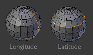
The left sphere shows an edge that was selected longitudinally. Notice how the loop is open. This is because the algorithm hit the vertices at the poles and terminated because the edge at the pole connects to more than 3 other edges. However, the right sphere shows an edge that was selected latitudinally and has formed a closed loop. This is because the algorithm hit the first edge that it started with.
Technical Details
The algorithm for selection is as follows:
- First check to see if the selected element connects to only 3 other edges.
- If the edge in question has already been added to the list, the selection ends.
- Of the 3 edges that connect to the current edge, the ones that share a face with the current edge are eliminated and the remaining edge is added to the list and is made the current edge.
See Also
Displacement Maps
Panel: Material buttons → Map To
Hotkey: F5
Description
Displacement mapping allows a texture input to manipulate the position of vertices on rendered geometry. Unlike Normal or Bump mapping, where the shading is distorted to give an illusion of a bump, this creates real bumps. They cast shadows, occlude other objects, and do everything real geometry can do.
Options
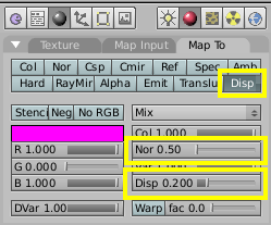
The strength of the displacement is controlled with the number fields Disp and Nor.
- If a texture provides only normal information (e.g. Stucci), vertices move according to the texture's normal data. The normal displacement is controlled by the Nor slider.
- If a texture provides only intensity information (e.g. Magic, derived from color), vertices move along the directions of their normals (a vertex has no normal itself, it's the resulting vector of the adjacent faces). White pixels move outward in the direction of the normal, black pixels move in the opposite direction. The amount of displacement is controlled with the Disp slider.
The two modes are not exclusive. Many texture types provide both information (Cloud, Wood, Marble, Image). The amount of each type can be mixed using the respective sliders. Intensity displacement gives a smoother, more continuous surface, since the vertices are displaced only outward. Normal displacement gives a more aggregated surface, since the vertices are displaced in multiple directions.
The depth of the displacement is scaled with an object's scale, but not with the relative size of the data. This means if you double the size of an object in object mode, the depth of the displacement is also doubled, so the relative displacement appears the same. If you scale inside editmode, the displacement depth is not changed, and thus the relative depth appears smaller.
Hints
Displacement maps move the Render Faces, the final rendered geometry after subdivision. To give a smooth, detailed surface, the faces have to be very small. This eats memory and CPU time.
From best to worst, displacement works with these object types using the methods listed to control the render face size:
- SubSurf Meshes
- Render face size is controlled with render subsurf level. Displacement really likes smooth normals.
- Simple SubSurf meshes
- Control render faces with render subsurf level. There is a pitfall at sharp edges however if the texture there is not neutral gray.
- Manually (editmode) subdivided meshes
- Control render faces with number of subdivides. (This can be combined with the above methods.) Displaces exactly the same Simple Subsurf, but slows editing down because of the OpenGL overhead of drawing the extra faces. (You can't turn the edit subdivide level down this way).
- Control render faces with render wiresize. Small wire == more faces.
The following are available, but currently don't work well. It is recomended that you convert these to meshes before rendering.
- Open Nurbs Surfaces
- Control render faces with U/V DefResolu. Higher numbers give more faces. (Note normal errors).
- Closed Nurbs Surfaces
- Control with DefResolu control. (Note the normal errors, and how implicit seam shows).
- Control with DefResolu control. Higher gives more render faces. (Note that the large flat surfaces have few renderfaces to displace).
Examples
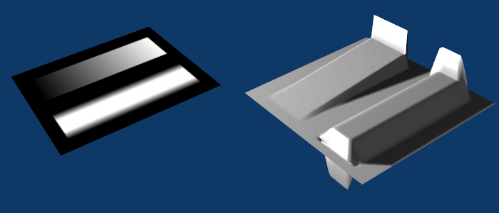
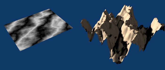
At first a not-so-well working example (Texture and Displacement Map):
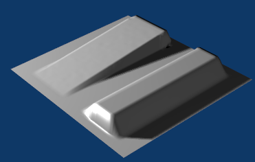
The sharp contrasting transitions from black to white yield problems. To correct this, use a little bit of gaussian blur on the texture (A blurred Texture).
If you use a Texture (like Marble) with no sharp transitions, the displacement works quite well (A Displacement Map to create a landscape).
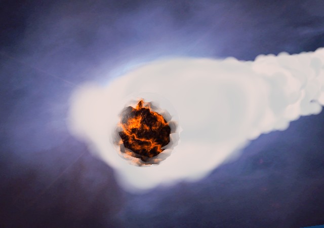
Advanced Materials often use Displacement Maps. Here a Marble Texture was applied to various Map To values, including Disp. The brink of the "comet" would be flat otherwise (A Displacement Map for advanced materials). The sphere has 1024 faces.
