Attic:Manual/Unwrapping 2.45
The first step is to unwrap your mesh. You want to unwrap when you feel your mesh is complete with respect to the number of faces it needs to have. If you do add faces or subdivide existing faces when a model is already unwrapped, Blender will add those new faces for you. In this fashion, you can use the UV Texture image to guide additional geometry changes.
The UV tools were significantly enhanced for Version 2.46. For users of Blender 2.45 and before, consult this archived page
Getting Started
UV Mapping is done in Blender within the UV/Image Editor window and a special mode in the 3D View window called UV Face Select. To begin, choose the SR:3-Material screen layout from the selection list at the top of your screen in the User Preferences window header, and set one of the panes to show you the UV/Image Editor window, and another pane the 3D window.
The UV/Image Editor allows you to map textures directly to the mesh faces. The 3D View window shows you the object being textured. If you set this window into Textured viewport shading, you will immediately see any changes made in the UV/Image Editor window in this window, and vice versa.
You can play with UV textures in Blender without a material, and still see them in the 3D window. To render an image however, you must
- create a Material for the object, and
- tell Blender to use the UV Textures on faces when rendering.
There are two ways to do this: the Proper way and the Quick Way.
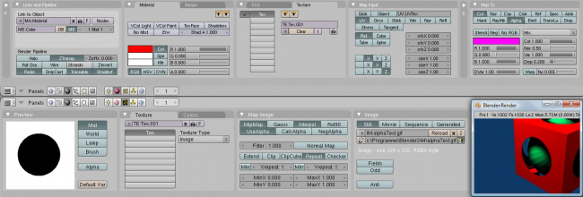
Either way, you have to click Add New Material. In the Texture channel panel F6((shown above), Add a New Texture which is mapped to the UV texture (it will be mapped to Color by default, and the UV Texture is named "UVTex" by default). Select the Textures subcontext, and define the texture as an image and load the image you want to use. If the image has an alpha channel and you want to use it, click "UseAlpha" in the Map Image panel.
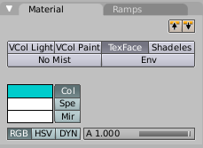
The quick way is to set up a TexFace Material as shown. To do so, with the buttons window displayed, press F5 to display the Shader Buttons. In the Buttons window, Material settings, click ADD NEW material. On the Material panel, enable TexFace. This way is quick, but bypasses the normal rendering system for fast results, but results which do not respect transparency and proper shading.
Material is Required for Rendering
You can perform UV Texturing on a mesh within Blender without assigning a material, and you will even see it in your 3D View in textured viewport mode. However, when you render, you will just get a default gray if the object does not have a Material assigned. You will get a black if you do not load an image. If you do not create a texture that uses the image, or enable TexFace, your object will render according to the procedural material settings.
|
Unwrapping
Each face of a mesh can have many UV Texture coordinates and an individual image assigned to it for each UV Texture. When you unwrap a face from UV Face Select mode to a UV Texture in the UV/Image Editor, each face of the mesh is automatically assigned two extra internal features:
- four UV coordinates These coordinates define the way an image or a texture is mapped onto the face. These are 2D coordinates, which is why they're called UV, to distinguish them from XYZ coordinates. These coordinates can be used for rendering or for realtime OpenGL display.
- a link to an Image Every face in Blender can have a link to a different image. The UV coordinates define how this image is mapped onto the face. This image then can be rendered or displayed in realtime. A 3D window has to be in "Face Select" mode to be able to assign Images or change UV coordinates of the active Mesh Object.
UV Face Select Mode
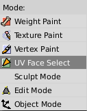
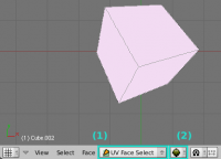
Go into UV Face Select mode using the mode selector in the 3D View window header. Notice that all of your 3D windows go into this mode as well. If you enter the Textured draw mode (AltZ) - also called "potato mode" - you will see your mesh drawn in white (like a peeled potato), which indicates that there are no images assigned to these faces.
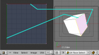
If the mesh does NOT already have a UV Texture (in other words, this is its first time in UV Face Select mode), a reset unwrap of the entire mesh is instantly created. This reset unwrap maps every face, regardless of size, to the full image space. All of the UV Coordinates for the faces are stacked on top of one another in the UV/Image Editor.
When you select a white face that has not been mapped, it gets a little embarrased and blushes (turns pink). In the example to the right, all faces are selected and none have been mapped, so they are all pink.
Active Face
The last face clicked is "active" (either selected via right-click or de-selected thru shift-right-click). If you select some faces, then de-select some others, the last face you de-selected is "active". If the active face is a de-selected one, you will not be able to map it or see it's UV Texture, since, well, it isn't selected. All other faces that are selected are mapped though; just click on them to see their mapping.
|
UV Orientation
To map a single face to a UV image, select it from within UV Face Select mode in your 3D window by RMB ![]() clicking on a face of the object. If the face was white and turns pink when you click, it means that there currently is no UV mapping for it.
clicking on a face of the object. If the face was white and turns pink when you click, it means that there currently is no UV mapping for it.
You might have noticed a change in the UV/Image Editor window. The display has been outlined, with the top in red, and the side in green. If you look closely at your 3D window, you will see that the an edge of the face is highlighted in red, and another perpendicular to it is in green. These colored edges help you orient yourself to the image that will be displayed on it.
If you don't like the orientation, for example if the picture is on its side or upside down, press R to Rotate the mapping by 90 degrees (120 degrees if a triangle) with each R keypress.
Mapping an Image to Your UVs
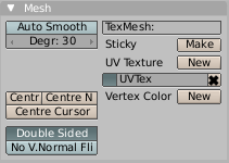
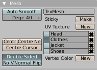
When you entered UV Face Select mode, Blender created a mapping in the UV/Image editor window. If you examine your Editing (F9) buttons, the Mesh panel, you will see a new UV Texture entry, called "UVTex" by default. This panel section has a button to the left of the name, used to select the UV Texture map if there are many listed. The name can be changed by clicking into the field and typing. This texture map can be deleted by clicking the X. You can add arbitrary UV Textures by clicking New, but you will rarely have to, since Blender creates them automatically each time you unwrap.
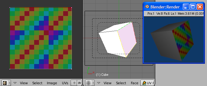
Let's assign an internally generated image to this UV Layout. We will call that image a "UV Texture" once it is texture mapped. First, we have to create the image in memory. With the faces selected in the 3D window, move on over to the UV/Image Editor window. From the header menu, select Image->New. Here you select the size of the image to be used, and/or a test grid. Use the Test Grid to orient yourself to the direction of the UV mapping. If you select Test Grid and click OK, that image of the test grid is mapped to the faces. It cannot be rendered yet, because we have not told Blender how to reflect the light off the object when rendering. We do that by creating a Material Texture.
First, Add New material for the object. In the Material Texture tab, click Add New and a texture called "Tex" will be created and assigned to the top channel. In the Map Input panel, specify we want to use our UVTex UV-map, and map the texture to Col (which is selected by default). So, we have told Blender to color the surface of the mesh with a texture, but we haven't told Blender which texture to use.
Activate the Texture subcontext buttons, and load the UV image by clicking the the Load button in the Image panel.
A quick render will show that you have automatically mapped the color of the faces of the mesh to an image used as a UV texture. Congratulations!
These three links are crucial to understanding:
- A UV Layout, shown in the UV/Image Editor, that maps mesh faces to all or part of the image workspace,
- A Material assigned to those faces which maps a texture to the colors, and
- An image texture which loads an image.
Now here comes the confusing part: a mesh object can have many UV Layouts (listed in the Editing buttons panel, UV Texture list). A mesh object can have multiple materials, with a single material mapped to one or more faces of the object. A material can have many (up to 10) textures, each assigned to a texture channel. Each of those textures can be an image mapped to a UV Texture. So, Blender provides ultimate flexibility in mapping and layering images to faces of a mesh object.
You do not have to map all faces to an image. If you select the top face of the cube in UV Face Select mode, then Select->Inverse, you will have selected all the faces except the top one. Then, in the UV/Image Editor window, select a different image. Of course, instead of creating a new image, you can load any of the image formats supported by Blender (JPG, PNG, TGA, etc.)
Once a face has been mapped, RMB ![]() clicking on that face in the 3D View will cause the UV/Image Editor window to automatically show the image and UV coordinates for the selected face. The UV map for that face will be selected in the Mesh panel.
clicking on that face in the 3D View will cause the UV/Image Editor window to automatically show the image and UV coordinates for the selected face. The UV map for that face will be selected in the Mesh panel.
Unwrapping Using Seams
For most cases, using the Unwrap calculations of Cube, Cylinder, Sphere, or best fit will produce a good UV layout. However, for more complex meshes, especially those with lots of indentations, you may want to define a seam to limit and guide any of the unwrapping processes discussed above. Just like in sewing, a seam is where the ends of the image/cloth are sewn together. In unwrapping, the mesh is unwrapped at the seams.
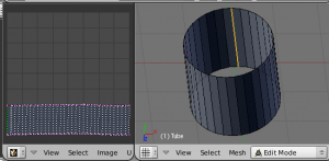
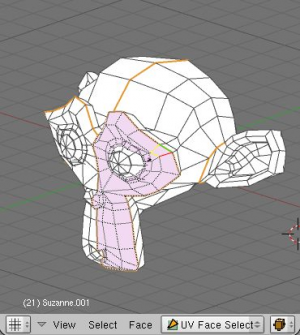
The easiest way to define a seam is Edge selection in Edit Mode. Select the edge(s) that define the seam with border or ⇧ ShiftRMB ![]() , and press CtrlE or use the Mesh->Edges->Mark Seam menu. In the example to the right, the back-most edge of the cylinder was selected as the seam (to hide the seam), and the default unwrap calculation was used. In the UV/Image Editor window, you can see that all the faces are nicely unwrapped, just as if you cut the seam with a scissors and spread out the fabric.
, and press CtrlE or use the Mesh->Edges->Mark Seam menu. In the example to the right, the back-most edge of the cylinder was selected as the seam (to hide the seam), and the default unwrap calculation was used. In the UV/Image Editor window, you can see that all the faces are nicely unwrapped, just as if you cut the seam with a scissors and spread out the fabric.
When marking seams, use the Select->Linked Faces in UV Face Select Mode to check your work. This menu option selects all faces connected to the selected one, up to a seam. If faces outside your intended seam are selected, you know that your seam is not continuous.
To add an edge to a seam, simply select the edge and CtrlE Mark Seam. To take an edge out of a seam, select it, CtrlE and Clear Seam.
You do not have to select continuous seams. If you select one edge, and follow that line and select another edge further down the line using Shift + Alt + RMB ⇧ ShiftAltRMB ![]() on the edges in UV face select mode, Blender will connect the line and select all edges in between.
on the edges in UV face select mode, Blender will connect the line and select all edges in between.
Just as there are many ways to skin a cat, there are many ways to define seams. In general though, you should think as if you were holding the object in one hand, and a pair of sharp scissors in the other, and you want to cut it apart and spread it on the table with as little tearing as possible. Note that we seamed the outside edges of her ears, to separate the front from the back. Her eyes are disconnected sub-meshes, so they are automatically unwrapped by themselves. A seam runs along the back of her head vertically, so that each side of her head is flattened out.
Another use for seams is to limit the faces unwrapped. For example, when texturing a head, you don't really need to texture the scalp on the top and back of the head since it will be covered in hair. So, define a seam at the hairline. Then, when you select a frontal face, and then select linked faces before unwrapping, the select will only go up to the hairline seam, and the scalp will not be unwrapped.
When unwrapping anything that is bilateral, like a head or a body, seam it along the mirror axis. For example, cleave a head or a whole body right down the middle in front view. When you unwrap, you will be able to overlay both halves onto the same texture space, so that the image pixels for the right hand will be shared with the left; the right side of the face will match the left, etc.
Unwrapping Multiple Faces
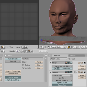
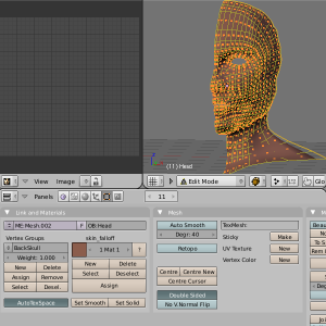
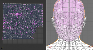
In general, you should only unwrap the faces you need to, and do so in a single unwrap operation. You only need to unwrap faces that will be painted using an image; all other faces can use procedureal materials and textures or vertex paint. You want to keep your image as small as possible, so that means you want to keep the number of faces as small as possible. For example, if the body is always going to be covered in clothes or armor, there is no need to unwrap it. If the back of the head is always going to be covered by hair, there is no need to unwrap the scalp. If you are modeling a chair with an embroidered seat cushion, you only need to unwrap the cushion and not the chair legs. In the example to the right, we only need to unwrap one side of the face, cutting our image size in half, so we leave mirror modifier on; we also do not need to double the number of UV coordinates by applying the Subsurf modifier; we can just leave it as is. Note that at this point, there is no UV Texture in the Mesh panel.
To unwrap multiple faces to a single UV Texture, there are two ways to select the faces you want:
- In Edit Mode (⇆ Tab), enter Face Select mode and select the faces you want.
- In UV Face Select mode using the 3D window, right-click or border select the faces you want.
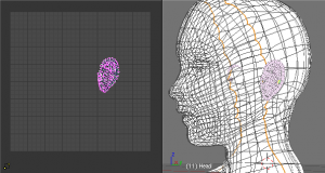
The example to the right shows that we have hidden many faces from view; the ears and the back of the head. We did so by creating and using the Vertex Groups, selecting the "BackSkull" group and Hiding them from view. We did this because we do not want to unwrap those areas, and we don't want them to get in the way during any further face selection that we may do.
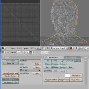
Once we enter UV Face Select mode, Blender creates a UV Texture map for us, shown in the Mesh panel, and displays that map in the UV/Image Editor Window. By default, the map is full-size reset overlay, which means that each selected face is mapped to the full size of the UV window, and the faces are overlaid on top of one another. This situation is identical to the above introduction where you mapped your first face of the cube; any face of the cube you clicked on would show this same full-size map; any image selected would be displayed on each face. If you were to assign an image now, you would see a patchwork style of render, much like the scene in the Matrix when Neo was in the TV room and saw himself tiled over and over. If we were to use an image that was tileable, the surface would be covered in a smooth repetition of that image, with the image skewed to fit the shape of each individual face. Use this unwrapping option to reset the map and undo any unwrapping (go back to the start).
If you did not select all desired faces prior to entering UV Face Select mode, you can select multiple additional faces in any of the following ways:
- Press A and all faces of the Mesh will be selected and highlighted by dotted lines.
- Select Linked faces from the 3D View menu; this will select additional faces up to a seam
- You can select many faces by ⇧ ShiftRMB
 clicking on each one you want. You may spin the object or your view of the object and resume selecting by ⇧ ShiftRMB
  .
. - BorderSelect in the 3D window.
- Enter EditMode and select the vertices or edges that define the face you want. After leaving EditMode and back in UV FAce Select mode, the faces defined by the selected vertices/edges will also be selected.
In UV Face Select mode, just like in Edit mode, you can also hide faces from view so they don't get in the way as you are trying to select faces:
- H to hide selected faces
- ⇧ ShiftH to hide the faces which are not selected, sort of the reverse of H by itself.
- AltH to reveal the hidden faces. Note that if you leave and then re-enter UV Face Select mode, they will be unhidden.
Only one face is considered active; the last one selected. Since the UV/Image Editor can only show one image at a time, it will show the image for the active face. IF you change the active face mapping (if you move the its UV coordinates), you may be overlapping or affect all other face mappings that are part of tha UV map (even if you cannot see them). So, before adjusting a face's UV coordinates, it is best to select adjoining faces to you see the whole map.
Face Unwrap using UV Calculation
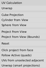
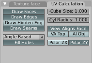
With our faces selected, it is now time to unwrap them to something more useful than Full-Size Reset. We want to unwrap them to the UV/Image Editor window using one of the UV Calculation shown to the right. In the 3D View header menu, select Face->Unwrap UVs or just press U. You can control the way the faces are mapped in two ways:
- Automatically using the 3D View window command Face->Unwrap UVs U
- Automatically using the UV/Image Editor window command UVs->Unwrap command E
- Creating seams and then unwrapping. A seam is marked in Edit mode by selecting edges that make the seam and then issuing the command to Mark Seam.
Above, when you selected a single face and went into Face Select Mode, Blender automatically mapped the selected face to the entire image for you, based on the face's UV orientation (the red and green borders). You can unwrap a face manually through the Face->Unwrap menu. How the selected faces map over to the image depends on the UV Calculation method that you choose.
The Face->Unwrap->Unwrap option unwraps the faces of the object to provide the 'best fit' scenario based on how the faces are connected and will fit within the image, and takes into account any seams within the selected faces. If possible, each selected face gets its own different area of the image and is not tucked under any other faces. If all faces of an object are selected, then each face is mapped to some portion of the image.
This point is crucial to understanding mapping later on: a face's UV image texture only has to use part of the image, not the whole image. Also, portions of the same image can be shared by multiple faces. A face can be mapped to less and less of the total image.
Based on the fundamental geometry of the object, and how it is viewed, the Face->Unwrap->Cube, Cylinder, and Sphere UV Calculations attempt to unfold the faces for you as an initial best fit. Here, the view from the 3D window is especially important. Also, the settings for cube size or cyclinder radius (Editing buttons, UV Calculation panel) must be set (in blender units) to encompass the object.
Normally, to unwrap a cylinder (tube) as if you slit it lengthwise and folded it flat, Blender wants the view to be vertical, with the tube standing 'up'. Different views will project the tube onto the UV map differently, skewing the image used. Also note the Polar coordinate axis selection buttons in the UV Calculation panel located in the Editing buttons window; they tell Blender which way is up.
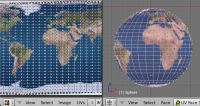
Recall the opening cartographer's approaching to mapping the world? Well, you can achieve the same here when unwrapping a sphere from different perspectives. Normally, to unwrap a sphere, view the sphere with the poles at the top and bottom. After unwrapping, Blender will give you a mercator projection; the point at the equator facing you will be in the middle of the image. A polar view will give a very different but common projection map. Using a mercator projection map of the earth as the UV image will give a very nice planet mapping onto the sphere.
In the 3D window, Face->Unwrap UVs->Project from View option maps the face as seen through the view of the 3D window it was selected from. It is almost like you had x-ray vision or squashed the mesh flat as a pancake onto the UV map. Use this option if you are using a picture of a real object as a UV Texture for an object that you have modeled. You will get some stretching in areas where the model receeds away from you.
In the 3D window, Face->Unwrap->Reset maps each selected face to the same area of the image, as previously discussed. To map all the faces of an object (a cube for example) to the same image, select all the faces of the cube, and unwrap them using the Reset menu option.
Note: The next four options create a UV map that stretches to maximum, and does not respect the image size. After using these options, you may have to zoom waaaaay out in the UV/Image Editor, select all UV coordinates, and scale them waaaaay down to fit inside the image area.
The Face->Unwrap->Click project from face is a three-step process that lets you orient the projection map according to a selected face's orientation. When selected, the upper User Information bar changes to display the step you are on, temporarily replacing the Blender version and statistics. The first click selects a bottom-left corner of that typical face. The second defines 'up' based on the face orientation, so click on the corner of that face that corresponds to the up direction from the first corner. The third click defines the V coordinate, namely which way is right on the map.
The Face->Unwrap->Follow Active (quads) takes the selected faces and lays them out perfectly square, even if the mesh face is irregularly shaped. Note that it does not respect the image size, so you may have to scale them all down a bit to fit the image area.
Use Face->Unwrap->UVs from unselected adjacent to expand your UV map by selecting un-mapped (new) faces and then this option. Blender will attempt to match up the coordinates of the new face with existing faces previously mapped. This option is helpful if you have added new faces and want to unwrap them.
Finally, the Face->Unwrap->Unwrap (smart projections), (which used to be called the Archimapper) gives you fine control over how automatic seams should be created, based on angular changes in your mesh. This option is especially well suited to unwrapping multiple mechanical objects all at once. The Archimapper is discussed a little later on.
Face Unwrap using the UV/Image Editor Menu
In the UV/Image Editor window menu, the menu item UVs also has a simple Unwrap option. There is no choice of different calculations to use; it is the same as selecting Face->Unwrap UVs->Unwrap in the 3D View. Use this option to unwrap additional faces with an existing set of unwrapped faces. The UV Coordinates for the addtional face will be added to the existing set in a non-overlapping manner. Warning: the UV coordinates for all of the faces will be recalculated.
Unwrap (smart projections)
An architype mapper (archimap) is the final but possibly the best option for unwrapping a mesh, even simple geometric forms. This function examines the shape of your object, the faces selected and their relation to one another, and creates a UV map based on this information and settings that you supply. In prior versions of Blender (pre-2.43), it was a script.
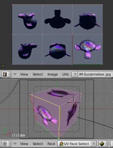
In the example to the right, the Archimapper mapped all of the faces of a cube to a neat arrangement of 3 sides on top, 3 sides on the bottom, for all six sides of the cube to fit squarely, just like the faces of the cube.
For more complex mechanical objects, this script can very quickly and easily create a very logical and straightforward UV layout for you.
Archimap allows you to unwrap multiple meshes in a single step (select multiple meshes in object mode). If you only have one mesh selected and are in Face Select mode, you can unwrap only selected faces, or if you select all the faces of the mesh, the whole object.
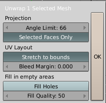
The popup panel allows the fine control over how the mesh is unwrapped. The angle limit controls how faces are grouped: a higher limit will lead to many small groups but less distortion, while a lower limit will create less groups at the expense of more distortion.
Archimap prefers you to have an image loaded if you want to Stretch to Bounds. When you use an image for a UV Texture, sometimes the edges of the image won't align perfectly or there will may be a border around the outside of the image. The Bleed Margin will shrink the overall UV coordinate map so that this margin is not mapped or used as UV Texture. For complex meshes, Archimap may create (by default) a map that has holes in it, resulting in wasted space in the image. Selecting Fill Holes will cause Archimap to do a little more work at ensuring each face is mapped as large as possible and that there are fewest holes (wasted image texture pixels) possible.
Combining UV Maps
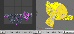
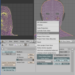
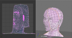
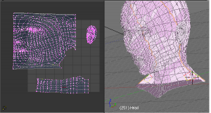
Very often you will unwrap an object, such as the face example we have been using, and get it 'mostly right' but with parts of the mesh that did not unwrap properly, or are horribly confusing. The picture to the right shows an initial unwrap of the face using the Unwrap from sphere option. The issues are with the ear; it is just a mush of UVs, and the neck, it is stretched and folded under. Too much work to clean up.
We can tell that the ear would unwrap nicely with just a straightforward projection from the side view, and the neck with a tubular unwrap. So, we have to unwrap part of an object using one unwrap calculation, and the rest using another calculation. We select only the face faces, unwrap them using the Sphere calculation, and scale and rotate them somewhat to fit logically within the image area of the UV/Image Editor window pan.
For the next part of the mesh, unselect the faces you were working with. Their UVs will disappear, but they are still there, just not show. To verify this, you can select a few faces in 3D view and it will show up in the UV/Image Editor.
To work on the ear, in the 3D View, we select only the ear faces. You can switch out of UV Face Select mode, into Edit mode, and use Vertex Groups to select the ear. Selecting sub-meshes is easy too, since they are not connected to the rest of the mesh, simply selecting Linked vertices will select that entire submesh.
Back in UV Face Select mode, re-unwrap the ear using the Project calculation, scale and rotate them somewhat (discussed in the next section), and place them off to the side. You can do this repetitively, using different UV calculations; each re-calculation just puts those UVs somewhere else. Choose the calculation that gives you the best fit and most logical layout for subsequent painting.
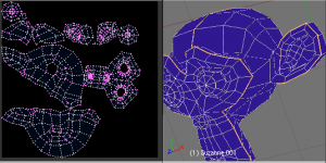
When all parts of the mesh have been unwrapped using the various calculations, you should end up with something that looks like to the Example to the right. All of the sections of the mesh have been mapped, and all those maps are laid out in the same UV Texture map. Congratulations! From here, it is a simple matter of stitching (discussed in the next section) to construct the entire UV Map as a single map.
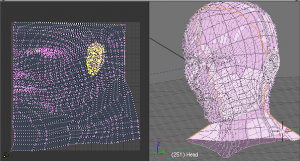
When you have completed arranging and stitching, you will end up with a consolidated UV Map, like that shown to the right, arranged such that a single image will cover, or paint, all of the mesh that needs detailed painting. All of the detailed instructions on how to do this are contained in the next section. The point of this paragraph is to show you the ultimate goal. Note that the mesh shown is Mirrored along the Z axis, so the right side of the face is virtual; it is an exact copy of the right, so only one set of UVs actually exist. If more realism is desired, the Mirror modifier would be applied, resulting in a physical mirror and a complete head. You could then make both side physically different by editing one side and not the other. Unwrapping would produce a full set of UVs (for each side) and painting could thus be different for each side of the face, which is more realistic.
Multiple UV Layouts
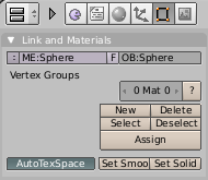
You are not limited to one UV Layout per mesh. You can have multiple UV layouts for parts of the mesh by creating new UV Textures. The first UV Texture is created for you when you select a face in UV Face Select mode. You can manually create more UV Textures by clicking the New button next to "UV Texture" on the Mesh panel in the Buttons Window, Editing Context) and unwrapping a different part of the mesh. Those faces will then go with that UV Texture, while the previously unwrapped faces will still go with the previous UV Texture. Note that if you unwrap the same face twice or more times (each time to a different UV Texture), the coloring for that face will be the alpha combination of the layers of those UV Textures.
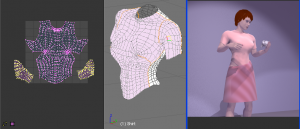
In the example to the right, we have a mesh for a blouse. The mesh has been seamed as a normal blouse would, shown in the middle in UV Face Select mode. Wishing to make a cut pattern, the front of the blouse was unwrapped and basic rotation and scaling was done to center it in the UV/Image Editor window. It was then moved off to the side, while the left and right sleeves were unwrapped, each rotated and scaled. Then, select a sample face from each cloth piece, in the 3D View Select->Linked Faces, and the UV/Image Editor will show all those pieces (as shown to the right). You can then work with all pieces for that UV Texture layout. The example shows all three pieces moved onto the image area for painting. As you can see, the pattern nicely fits a square yard of cloth.
Another UV Layout was created by clicking the New button in the Mesh panel, and the process was repeated for the backs of the sleeves and the back of the blouse. Two images, one for the front and one for the back, are used to color the fabric. In this case, some faces map to the first texture, while other faces map to the second texture.
Additional Options
When you switch your 3D window to UV Face Select mode, Blender changes the menu slightly to give you more and better tools to use.
Similar to Active: The Select menu now offers a script to help you select items that are similar to the last-selected (active) face. You can pick all the faces, for example, that have the same surface area (plus or minus a limit) as the active one. For each choice, you can add or take away the similar items from the list of faces selected. Criteria include Material, UV Image, Face mode, Vertex colors, and many others. For example, if you were going to change an image used as a UV texture, you would want to select all faces that used that same UV image in order to evaluate the impact of the change on the overall mesh.
Linked Faces: Recall that not all faces and vertices of a mesh have to be connected. A single mesh can be composed of many disconnected sub-meshes. Selecting Select->Linked Faces is useful for selecting all the faces of a submesh. Also, linking goes up to a seam as previously discussed.
Set Vertex Colors: If you don't like potato white, select Set Vertex Colors to view your mesh using the active color of Vertex Paint. A blue face color contrasts the seam colors nicely.
Editing Buttons
In the Buttons window, press F9 to get the Editing buttons. When in UV Face Select mode, the buttons change to give you additional options when working with UV maps. The AutoTexSpace button should be enabled.
UV Textures List
The Mesh panel (shown to the right) clearly lists the UV Texture maps created for this mesh, and allows you to create New ones as placeholders for future unwrapping operations. Each map has a selector button, a name, and a fat X Delete button. The selected map is displayed in the UV/Image Editor window. The example shows a few UV maps created for a character, and the map for Clothes is selected.
Deleting a UV layout for the mesh destroys all work done in all unwrapping associated the mesh. Click with care. You've been warned.
UV Texture Options
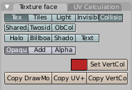
The Texture Face panel is added when you go into UV Face Select mode, so you are not used to seeing it. Lots of neat options for controlling how the UV texture interacts with the rest of your scene. Options for how and if it is shown include: Tex, Tiles, Light, and Invisible. You almost always want it to participate in object and particle Collisions. The texture can be Shared, rendered front and back (Two Sided), and, where blank, can be shown using the object (not the vertex painted) colors.
The texture can color Halos, or be shown like a Billboard, or normally with neither of these selected. The face can used to cast Shadows on other objects.
When rendered, Opaque lets you see this texture, which is almost always a good idea. If you want sections to be transparent where the texture is, use Add; to use the texture as an alpha mask, use Alpha.
Copy UV+ is an action button, not a setting. It copies the UV mapping from the active face (the last face selected) to all other faces that are selected. Select all faces you want similarly mapped first, then ⇧ ShiftRMB ![]() the model face, and click Copy UV+
the model face, and click Copy UV+
Drawing options (how the UV mapping looks to you while working in Blender) include drawing Faces, Edges, Hidden Edges, and Seams. When you project from a view, normally the View Aligns Face, but you can specify that, for unwrapping round objects (tubes and spheres), the view is aligned to the top (poles) of the object.
By default, Unwrap uses the Angle-Based Formula, or ABF. If you want to use Least-Squares Conformal Method (LSCM) instead, change Angle-Based to Conformal. The reason why ABF is default is because it is generally better than LSCM. There may be some exceptions for that though, so if an unwrap just isn't clean to you, try conformal.
Please set the cube and tube sizings to encompass your object prior to unwrapping, or incredible skewing and sizing will result.
Saving your UV Layout
The UV coordinates and image links are automatically saved with the mesh in the .blend file. There is nothing extra you need to do.
Saving an outline of your UV Layout
As a way of communicating to an artist who is painting your UV Texture for you, Blender offers a script called Save UV Face Layout (located in the UV/Image Editor Window, UVs->Scripts->Save UV Face Layout) that saves an image in Targa format (.tga) for the object you have selected. The image is an outline of the UV face mapping. The file is (by default) named with the prefix you enter. If Object name is enabled, then the name of the object is appended on so that you don't accidentally overwrite one layout for one object with another's.
Controls allow you to:
- Size
- select the size of the image in pixels. The image is always square
- Wire
- the thickness of the wire lines that define each face border
- All Faces
- if disabled, then only the UV faces selected will be outlined
- SVG
- if enabled, saves the file as a scalable vector graphic (SVG) format file, not a Targa.
- Fill SVG faces
- fills in SVG faces to allow easier editing and face recognition
- Edit
- Enabling Edit and specifying the name of an editing program int eh Editor: field will launch that program and load in the saved layout (after the image has been saved).
The image will be lines defining the UV edges that are within the image area of the UV mapping area. Edges outside the boundary, even if selected, will not be shown in the saved graphic.
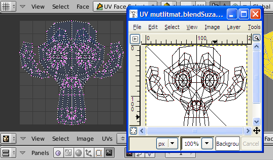
The artist will use this as a transparent layer in their paint program as a guide when painting your texture. The example below shows Blender in the background, and the Gimp working on the texture, using the saved layout as a guide. Note that targa format supports the Alpha channel, so you can paint transparent areas of the mesh.
