利用者:Greylica/Doc:2.6/Manual/Modeling/Meshes/Editing/Duplicating/Screw
Screw Tool
Mode: Edit Mode
Panel: Edit Mode → Mesh Tools (shortcut T) → Add → Screw Button
| Small bug has been found | |
| When writing this page, a small bug has been found in Blender version 2.65 and the steps division get messy. The bug has been fixed by Sebastien Montagne in less than 4 hours after filling a bug report. Any Blender version since release 53090 is working. When following this page, plesase download a newest build from Graphicall.org suitable for your system, this warning should be removed after 2.65a or 2.66 official launch |
Introduction
The Screw Tool is one of the most used tools for generating continuous circular profiles in Blender since its ancient versions because the generated profiles are very predictable, light to deal with, and well connected. This tool helps artists generate clean circular profile meshes.
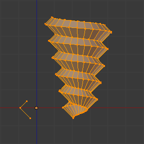
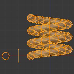
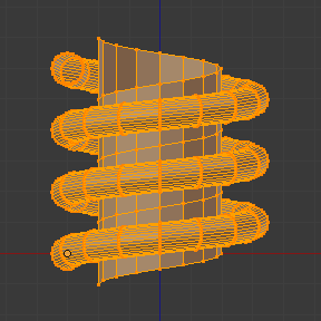
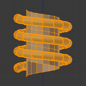
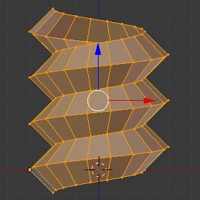
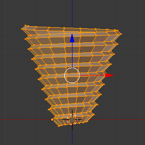
You can see some examples of Meshes generated with the Screw tool in the Fig. 1 – Wood Screw tip done with the screw tool and Fig. 2 – Spring done with the screw tool.
Description
The Screw tool combines a repetitive Spin with a translation, to generate a screw-like, or spiral-shaped, object. Use this tool to create screws, springs, or shell-shaped structures (Sea shells, Wood Screw Tips, Special profiles, etc).
The main difference between the Screw Tool and the Screw Modifier is that the Screw Tool can calculate the angular progressions using the basic profile angle automatically or adjusting the Axis angular vector without using a second modifier (For example, using The Screw Modifier with Bevel Modifier, Curve Modifier, etc...), resulting in a much cleaner approach for vertex distribution and usage.
Usage
- This tool works with only with Meshes.
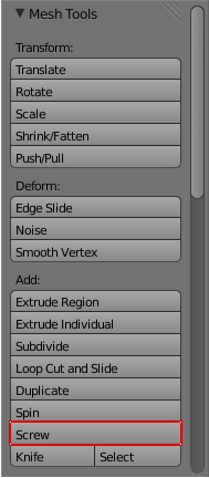
- Enter Edit Mode, the button for the Screw tool operation will be located at the Mesh Tools Panel, (shortcut T) → Add → Screw Button.
- To use this tool, you need to create at least one open profile or line to be used as a vector for the height, angular vector and to give Blender a direction.
- The Screw function uses two points given by the open line to create an initial vector to calculate the height and basic angle of the translation vector that is added to the “Spin” for each full rotation (see examples below). If the vector is created with only two vertices at the same X, Y and Z location (which won't give Blender a vector value for height), this will create a normal “Spin”.
- Having at least one vector line, you can add other closed support profiles that will follow this vector during the extrusions (See limitations).
- The direction of the extrusions is calculated by two determinant factors, your point of view in Global Space and the position of your cursor in the 3DView Space using Global coordinates.
- The profile and the vector must be fully selected in the Edit Mode before you click in the Screw Button (See Limitations.)
- When you have the vector for the open profile and the other closed profiles selected, click in the Screw Button.
Limitations
There are strict conditions about your profile selection when you want to use this tool. You must have at least one open line or open profile giving Blender the starting Vector for extrusion, angular vector and height. (e.g. a simple edge, a half circle, etc…).
You need only to ensure that at least one reference line has two “free” ends. If two open Lines are given, Blender won't determine which of them is the vector, and will then show you an error message, “You have to select a string of connected vertices too”.
You will need to select all of the profile vertices that will participate in the Screw Tool operation, if they are not properly selected, Blender will also show you the same message.
Note that the open line is always extruded, so if you only use it to “guide” the screw, you will have to delete it after the tool completion (use linked-selection, CtrlL, to select the whole extrusion of the open line).
If there is any problem with the selection or profiles, the tool will warn you with the error message: “You have to select a string of connected vertices too” as seen in Fig. 3 and 4, both in the info Window and at the place where you clicked to start performing the operation (when you click in the Screw Button).
You may have as many profiles as you like (like circles, squares, and so on) – Note that not all vertices in a profile need to be in the same plane, even if this is the most common case. You may also have other, more complex, selected closed islands, but they have to be closed profiles because Blender will seek for only one open profile for the translation, height and angular vector. Some closed meshes that overlap themselves might not screw correctly (For example: Half UVsphere is OK, but more than half could cause the Screw Tool to have a wrong behavior or errors), and profiles that are closed with faces (like a cone or half spheres) will be closed automatically at their ends, as if you were extruding a region.
| Simple way to not result in error | |
| Only one open Profile, all of the others can be closed, avoid volumes with more than half regions... |
Options
This tool is an interactive and modal tool, and only works in the Edit Mode.
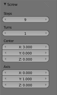
Once you click in the Screw tool in the Mesh Tools Panel, Blender will enter in the Screw interactive mode, and the Operator Panel at the end of the Mesh Tools Panel will be replaced where you can adjust the values explained below. To show the Mesh Tools Panel, use the shortcut T in the Edit Mode of the 3D View Window.
(See Fig. 5 - Screw Tool in the Mesh Tools Panel (Edit Mode), red box)
Once you perform any other operation, Blender leaves the interactive mode and accepts all of the values. Because it's modal, you can't return to the interactive mode after completing/leaving the operation or changing from Edit Mode to Object Mode. If you want to restart the operation from it's beginning, you can hit CtrlZ at any time in Edit Mode, or leave the Steps and Turns values with a value of 0 (Zero) which won't perform any Screw operation.
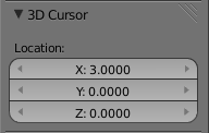
- The basic location of the cursor at the point of view (using Global coordinates) will determine around which axis the selection is extruded and spined at first (See Fig. 6 - Cursor Basic Location - Transform Panel). Blender will copy your cursor location coordinates to the values present in the Center values of the Screw interactive Panel. Depending on the Global View position, Blender will automatically add a value of 1 to the one of the Axis Vectors, giving the profiles a starting direction for the Screw Operation and also giving a direction for the extrusions. (see examples below)
- The position of the 3D cursor will be the starting center of the rotation. Subsequent operations (E.G. pressing the Screw button again), will start from the last selected element. Continuous operations without changing selection will repeat the operation continuously from the last point.
- Center
- Those numeric fields specifies the center of the spin. When the tool is called for the first time, it will copy the X, Y and Z location (Global Coordinates) of the cursor present in the 3D View to start the operation. You can specify the cursor coordinates using the Transform Panel in 3D View, using shortcut T to toggle the Panel, and typing in the 3D Cursor Location coordinates but, unlike in previous Blender Versions (prior to 2.5x), now you can adjust those coordinates interactively and specify another place for the spin center during the interactive session. (See Fig. 7 - Screw Interactive Panel - Mesh Tools Panel (Edit Mode))
- Steps
- This numeric field specifies how many extrusion(s) will be done for each 360° turn. The steps are evenly distributed by dividing 360º by the number of steps given. (See Fig. 7)
- Turns
- This numeric field specifies how many turns will be executed. Blender will add a new full 360° turn for each incremental number specified here. (See Fig. 7)
- Axis
- Those 3 numeric fields vary from -1.0 to 1.0 and are clamped above those limits. Those values are corresponding to angular vectors from -90 to 90 degrees. Depending on the position you started your cursor location and Object operation at the viewport and it's axis positions in Global View space and coordinates, Blender will give the proper Axis vector a value of 1, giving the angular vector of the profile a starting direction and giving the extrusions a starting direction based on your view. Blender will let you adjust your axis angular vectors and you can tweak your object in a way you can revert the direction of the screw operation (by reverting the angular vector of the height), meaning you can revert the clockwise and counterclockwise direction of some operations, and also adjust the angular vectors of your profile, bending it accordingly. (See Fig. 7)
Examples
The Spring example
- Open Blender and delete the default Cube.
- Change from perspective to ortographic view using shortcut Numpad5.
- Change your view from User Ortho to Front Ortho, using the shortcut Numpad1, you will see the X (red) and Z (blue) coordinate lines.
- In case you have moved your cursor clicking anywhere in the screen, place again your cursor at the Center, using the shortcut ⇧ ShiftS choosing Cursor to Center or the Transform Panel, placing your cursor at (0,0,0) typing directly at the Cursor 3D Location.
- Add a circle using shortcut ⇧ ShiftA and choosing → Mesh → Circle.
- Rotate this circle using the shortcut RX and typing 90 and ↵ Enter.
- Apply the Rotation using CtrlA and choosing Rotation
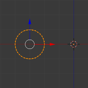
- Grab this circle to the left 3 Blender Units in the X Axis, you can use the shortcut Ctrl while grabbing with the mouse using the standard transform widgets (clicking in the red arrow shown with the object and grabbing while using shortcut Ctrl until the down left info in the 3D View marks D. -3.0000 (3.0000) Global ), or press the shortcut GX and typing -3 and ↵ Enter. You can use the Transform Panel (toggled with the shortcut T , and type -3 and ↵ Enter at the Location too. (See the Fig. 8 - Circle placed at X -3,0,0).
- You will have to scale your circle using the shortcut S and typing .5, then ↵ Enter.
- Now enter Edit Mode using shortcut ⇆ Tab.
- De-select all vertices using the shortcut A.
Now we will create a height vector for Blender:
- Press Ctrl and Left click LMB
 near the circle, in more or less at the light grey line of the square above the circle, and, while still pressing Ctrl, Left Click LMB
  again in the grey line below the circle. You have created two vertices and an Edge, wich Blender will use as the first height and angle vector.
 - Now, in the Transform Panel, in the median, clicking in the Global coordinates, for the X, Y, and Z coordinates, put (-2, 0, -1).
- Right Click RMB
 in the other vertex, and again, type it's coordinates for to X, Y and Z to (-2, 0, 1). This will create a straight vertical line with 2 Blender units of Height.
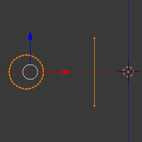
 - De-select and select everything again with the shortcut A. (See Fig. 9 - Profile and vector created)
- Place again your cursor at the center, (Repeating the step 2)
- At this point, we will save this Blender file to recycle the Spring for another exercise, click with LMB
 in File, it is placed at the header of the Info Window, (At the top left side), and choose Save as, our sugestion is to name it as Screw Spring Example.blend and click in Save as Blender file. You can also use the shortcut ⇧ ShiftCtrlS to open the File Browser Window in order to save your Blender file.
 - Click Screw and adjust the Steps and Turns as you like and we have a nice spring, but now becomes the interesting part !
Clockwise and Counterclockwise using the Spring Example
Still in the interactive session of the Screw Tool, you will see that the Z Axis Value of the Screw Panel is set to 1.000, left click LMB ![]() in the middle of the Value and set this value to -1.000. At first, the Spring is being constructed in a Counterclockwise direction, and you reverted the operation 180 degrees in the Z Axis. This is because you have changed the angular vector of the height you have given to Blender to the opposite direction (remember, -90 to 90 = 180 degrees ?). See the Fig. 10 - Counterclockwise direction and Fig. 11 - Flipped to Clockwise direction.
in the middle of the Value and set this value to -1.000. At first, the Spring is being constructed in a Counterclockwise direction, and you reverted the operation 180 degrees in the Z Axis. This is because you have changed the angular vector of the height you have given to Blender to the opposite direction (remember, -90 to 90 = 180 degrees ?). See the Fig. 10 - Counterclockwise direction and Fig. 11 - Flipped to Clockwise direction.
It's also important to note that this vector is related to the same height vector axis used for the extrusion and we have created a parallel line with the Z Axis, so, the sensibility of this vector is in practical sense reactive only to negative and positive values because its aligned with the extrusion axis. Blender will clamp the positive and negative to its maximum values to make the extrusion follow a direction, even if the profile starts reverted. The same rule applies to other Global axis when creating the Object for the Screw Tool, it means if you create your Object using the Top View (Shortcut Numpad7 with a straight parallel line following another axis (for the Top View, the Y Axis), the vector that gives the height for extrusion will also change abruptly from negative to positive and vice versa to give the extrusion a direction, and you will have to tweak the corresponding Axis accordingly to achieve the Clockwise and Counterclockwise effect.
Vectors that aren't parallel with Blender Axis
The high sensibility for the vector doesn't apply to vectors that give the Screw Tool a starting angle (Ex: any non parallel vector), meaning Blender won't need to clamp the values to stabilish a direction for the extrusion, as the inclination of the vector will be clear for Blender and you will have the full degree of freedom to change the vectors. Our example is important because it only changes the direction of the profile without the tilt and/or bending effect, as there is only one direction for the extrusion, parallel to one of the Blender Axis
|
Bending the Profiles using the Spring Example
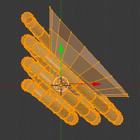
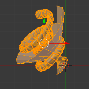
Still using the Spring Example, we can change the remaining vector for the angles that aren't related to the extrusion Axis of our Spring, thus bending our spring with the remainning vectors and creating a profile that will also open and/or close because of the change in starting angular vector values. What we are really doing is changing the starting angle of the profile prior to the extrusions. It means that Blender will connect each of the circles inclined with the vector you have given. below we show two bended Meshes using the Axis vectors and the Spring example. See Fig. 12 and Fig. 13. Those two Meshes generated with the Screw tool were created using the Top Ortho View.
Creating perfect Screw Spindles
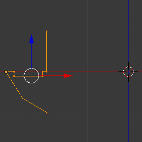
Using the Spring Example, it's easy to create perfect Screws Spindles (Like the ones present in normal Screws that we can buy in hardware houses). Perfect Screw Spindles uses a profile with the same height as their vector, and the beginning and ending vertex of the profile are placed at a straight parallel line with the axis of extrusion. The easiest way of achieving this effect, is to create a simple profile where the beginning and ending vertices create a straight parallel line. Blender won't take into account any of the vertices present in the middle but those two to take it's angular vector, so the spindles of the screw (which are defined by the turns value) will assembly perfectly with each other.
- Open Blender and click in File located at the header of the Info Window again, choose Open Recent and the file we have saved for this exercise. All of the things will be placed exactly the way you saved before. Choose the last saved Blender file, in the last exercise, we gave it a name, Screw Spring Example.blend.
- Press the shortcut A to de-select all vertices.
- Press the shortcut B, and Blender will change the cursor, you're now in border selection mode.
- Open a box that selects all of the circle vertices but the two vertices we have used to create the height of the extrusions in the last example.
- Use the shortcut X to delete them.
- Press the shortcut A to select the remaining vertices.
- Press the shortcut W for the Specials Menu, and select Subdivide
- Now, click with the Right Mouse button at the middle vertex.
- At this point, we will save this Blender file to recycle the generated Screw for another exercise, click with LMB
 in File, it is placed at the header of the Info Window, (At the top left side), and choose Save as, our sugestion is to name it as Screw Hardware Example.blend and click in Save as Blender file. You can also use the shortcut ⇧ ShiftCtrlS to open the File Browser Window in order to save your Blender file.
 - Grab this vertex using the shortcut GX, type -1 and ↵ Enter. See Fig. 14 - Profile for a perfect screw spindle.
- Press shortcut A twice to de-select and select all vertices again.
- Now Press Screw.
- Change Steps and turns as you like. The Fig. 15 - Generated Mesh - Shows you an example of the results.
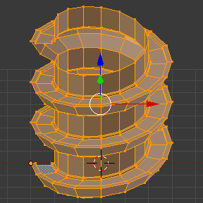
Here, in the Fig. 16 and Fig. 17, we show you an example using a diferent profile, but maintaining the beginning and ending vertices at the same position. The generated mesh looks like a medieval ramp !
As you can see, the Screw spindles are perfectly assembled with each other, and they are following a straight line from top to bottom. You can also change the Clockwise and Counterclockwise direction using this example, to create right and left screw spindles. At this point, you can give the screw another dimension changing the Center of the Spin Extrusion, making it more suitable to your needs or calculating a perfect screw and merging its vertices with a cylinder, modeling its head, etc.
A Screw Tip
Like we have explained before, the Screw tool generates clean and simple meshes to deal with, they are light, well connected and are created with very predictable results. This is due to the Blender calculations taking into account, not only the height of the vector, but also it's starting angle. It means that Blender will connect the vertices with each other in a way that they follow a continuous cycle along the extruded generated profile.
In this example, you will learn how to create a simple Screw Tip (Like the ones we use for wood, we have shown an example at the beginning of this page). To get this new example as small as possible, we will recycle our last example (again).
- Open Blender and click in File located at the header of the Info Window again, choose Open Recent and the file we have saved for this exercise. All of the things will be placed exactly the way you saved before. Choose the last saved Blender file, in the last exercise, we gave it a name, Screw Hardware Example.blend.
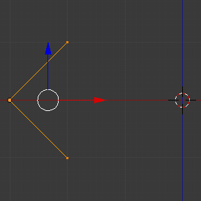
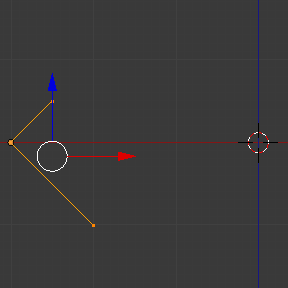
- Grab the upper vertex and move a bit to the left, but no more than you have moved your last vertex. (See Fig. 18 - Profile With Starting Vector Angle)
- Press the shortcut A twice to de-select and select all.
- Press the shortcut ⇧ ShiftS and select Cursor to Center
- Press Screw.
As you can see in Fig. 19, Blender follows the basic angular vector of the profile, and the profile basic angle determines wether the extruded subsequent configured turns will open or close the resulting mesh following this angle. The vector of the extrusion angle is determined by the starting and ending Vertex of the profile.
Screw Tool - Evolution since 2.5x
During the recode of Blender, from 2.4x to 2.5x series, the screw tool received lots of improvements. In Blender 2.4x series, the screw tool uses only one cursor position for its axis reference at a time, meaning you cannot tweak your object center changing the reference position without restarting the operation from its beginning. In 2.4x series, you also can't change the starting angular vector, the only one available was the vector that gives the clockwise and counterclockwise direction, and the angular vector of the tool during the screw operation coudn't be adjusted.
In 2.5x and above, you can not only change the reference position after it's chosen with the mouse cursor, using the interactive panel in the Mesh Tools in the Edit Mode (Shortcut T) to change the center during the interactive session, but you can also change the angular vector of the generated object by adjusts during the interactive session.
Another difference is that the clockwise and counterclockwise rotation of the Screw Tool now is determined by the axis vector tweak, meaning that you can change the direction of the screw rotation adjusting the corresponding X, Y and Z vector axis in positive and negative directions, it will depend on the orientation you have placed your object for creation and its center coordinates for spin and extrusion, we will explain the most common case in the examples of this page.
Blender will also determine automatically, depending on your view, the proper direction for the extrusion axis, meaning that you can change, at any time, the screw extrusion direction changing the global view alignement.
The rotation axis, still passing through the 3D cursor, is now free, but it's still preferable to align it with the y-axis of the view (i.e. up-down on the screen). So, the best way to start using this tool is to align your view with the front orthographic view using Numpad1 to create the Global height of the extrusions aligned with the Local Axis of your object. Blender will determine automatically your extrusion axis when you align your Vector with one of the Blender Global Axis, giving the proper axis vector a value of 1.
