Doc:2.6/Tutorials/Modeling/Modeling an android
Android of late is taking center stage and possibly everyone has a little bit of knowledge about it. Since it's won much interest in globally, I hope you'll enjoy following this tutorial that is dedicated to creating an android in Blender. This tutorial will not touch on the Android interface, however; we will be recreating the android logo (the machine-like toy that can be found on many android devices and online).
This tutorial is still basic and will enable you to find new ways of going about modeling objects and creating stuff. We'll be using the Mirror Modifier, adding a reference photo and using other modelling techniques. So let's get started.
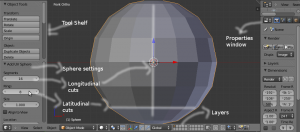
Delete the default cube in your 3D scene that comes up by default in Blender. Replace it with a Sphere as can be seen in the photo. To add the sphere, press [Ctrl + A >> Mesh >> Sphere]. We do not want the high number of vertices. So reduce them to somewhere around 16 Segments and 8 Rings. The rings are the latitude and the Segments are the longitude.
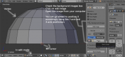
To make our modeling near to perfect, we'll have to include a reference photo to use. I grabbed one from Google Images by searching for Android. Now to include that in Blender, we'll have to use the option to add a Background photo. Press [N]. Locate Background Images and check it on. Press Add Image, locate the Android logo you saved onto your PC and open it into Blender. You should see the logo placed at the background of your 3D scene. You can only see the background photo when you are in Ortho versions of the front, top, side, and camera views. If you rotate your scene using the Middle Mouse Button, you will not be able to see the background photo. So take note.
Now, since we are creating the head of the android, select the bottom portion of the Sphere. To do that, [Tab] into Edit Mode, and using Box Select [B], select the vertices half-way down the Sphere as shown in the photo. Delete them to achieve something similar to what is in photo 2.
We have a reference photo in the background, so try to scale [S], and grab [G] your model around to position the truncated sphere on the head portion of the android logo in the background. Please don't add too many vertices (perhaps the current ones are enough) since we will be adding a subsurf (subdivision surface) modifier.
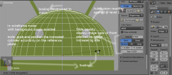
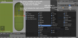
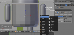
Okay, so that done, we have to get the hands and feet of the Android. Duplicate the truncated sphere [Shift + D]. Position the duplicated truncated sphere on the hand. Select the bottom vertices of the sphere and extrude [E] down. Don't worry about stretching it way down to the bottom of the hand; we're gonna use the Mirror Modifier. So look at image 3 and see how to go about it. I've extruded, and applied the Mirror Modifier. To add the Mirror Modifier, press on the Modifier tab in the Properties panel and select Mirror. Check the Z-axis to mirror the object in the Z-axis and uncheck the other axes (Y-axis and X-axis). If you are not seeing your mirroring like mine, it means you'll have to select all the vertices and Grab Constrained to Z-axis [G + Z] and move up. Now check Clipping in the Mirror options, as that will make the vertices which touch clip together and not overlap.
Its time to create the body of the Android. As usual, we'll be using a cylinder in achieving that. So [Shift +A >> Mesh >> Cylinder] and add the cylinder to your scene. Scale it up [S] and [G] Grab it to position it as in image 5. Grabbing around and scaling, try working out something similar to what's in image 5.
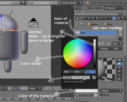
Our dear android is gradually taking shape. In image 6, mine is complete. For the meshes to look smooth, just click on the Smooth Shading option in the tool shelf after pressing [T]. Next, it's time to add our material color. Locate the Materials tab in the Properties panel and press the + button to add a new material. You can now see the preview of the default material applied to the selected object in your scene. You can change that color to anything of your choice and that's what we're gonna do next. Just below the preview box, click on the white rectangular box to bring up the color wheel. Click anywhere within the wheel to select the color of your choice. And you can use the vertical slider to increase or decrease the brightness and darkness of the material, respectively. Please select a color that's similar to the color of many android logos we see out there, including the background photo – green. Even though its green, it's not green mathematically, so use the color wheel to choose the precise color. It's a wheel, so drive it!
All the color changes we did affected one mesh only. How do we apply that same setting for other meshes in our scene? It's simple. Please select the next mesh you wish to apply the material color. Follow the same process in creating a new material. Then instead of doing the same color change settings all over again, we just click on the 'browse material to be linked' button, and select the name of the previously-created material.
Repeat the same process for the rest of the meshes. And now you should have something similar to my own in image 6. You couldn't do the same? Well, perhaps you can retry and see how best you can get as close to it as possible.
The last step is to position your camera correctly and render to get what I have in the final image at the beginning of this tutorial
Once again, we come to the end of another simple way to work on stuff in Blender. Happy Blendering
