利用者:Egtwobits
目次
- 1 Mesh Align Plus (Precision Modeling Addon) v0.2.0
- 2 Quick Start
- 3 Advanced Tools
- 4 Measuring Quantities and Composing New Items
- 5 Reference Manual
- 5.1 Available Transformations
- 5.2 Available Calculations
- 5.2.1 New Line from Point (Single Point)
- 5.2.2 Line Length (Single Line)
- 5.2.3 New Line from Origin (Single Line)
- 5.2.4 Get Plane Normal (Normalized), (Single Plane)
- 5.2.5 Distance Between Points (Point + Point)
- 5.2.6 New Line from Points (Point + Point)
- 5.2.7 New Line at Point (Point + Line)
- 5.2.8 Add Lines (Line + Line)
- 5.2.9 Subtract Lines (Line + Line)
- 6 Contact
Mesh Align Plus (Precision Modeling Addon) v0.2.0
This manual is for an older version. Visit the wiki and get the newest version here: Mesh Align Plus at Github
Mesh Align Plus is designed to help artists build 3D models from mesh pieces, and scenes from full objects, by precisely moving parts around in ways that were previously difficult or impossible.
Tragically, many common 3D tools are designed with only the global axis directions in mind (X, Y, Z). This makes even simple transformations that relate to specific parts of the artist's geometry difficult (rotating a part around a specified edge, for instance, or aligning a part so that one of its faces sits flat against another).
Efforts to solve these problems include (among others) "smart" auto-align tools, or snapping functions that try to guess what the artist wants, often with frustrating results. Beyond these, the artist is often left to 'eyeing it' until things look close enough (which is not sufficient in some cases).
The Mesh Align Plus addon gives users a way to tell the software *exactly* which part of their geometry they are interested in, and which kind of transformation they want to perform based off of it.
For those that like Blender Stack Exchange:
Quick align objects by face
Quick align objects by edge
Quick align objects by point
Quick axis rotation
Or see the full 30 minute demo video below:
https://youtu.be/ebEkfAQ4OOk
Installation
Download the latest production release from the releases page here (link). For each release, you'll see a "Downloads" section with some archives containing the addon. Extract and save the .py file containing the addon, then delete everything else...do not attempt to use/install directly from the zip file! The script follows the standard installation process for Blender addons (File > User Preferences > Addons > Install from File). Access Quick Tools for the addon in the Tools Panel (T) > Mesh Align Plus tab in the 3D view, and Advanced Tools in the Properties Editor > Scene Context, see below for details.
If you want to try out the latest new features, download the latest pre-release version (not from the releases page!) here (link) (use the "Clone or Download" > "Download Zip" button at the top right of the page, extract and save the .py file containing the addon, then delete everything else...do not attempt to use/install directly from the zip file!).
Quick Start
For those that want to jump in and get an immediate general sense of the addon's capabilities and usage patterns, a few quick demonstrations will be described in this section. *This manual assumes that readers already know how to use Blender.*
To keep these demos short and simple, only the addon's Quick Tools will be covered in this section (these are accessed from the 3D View > Tools Panel (T), Mesh Align Plus tab). The Quick Tools are designed to perform all of the most common operations an artist needs with the lowest number of clicks and setup, for maximum speed and ease of use.
For users who want more options or more fine grained control over their operations, or who want to work with imaginary geometry rather than real mesh geometry, use the addon's Advanced Tools, which are covered later in this manual (LINK).
A Simple Example
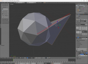
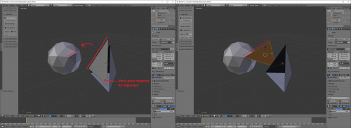
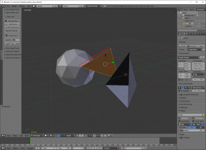
A very simple example would be aligning two objects by using an edge from each (here, taking a pyramid and aligning its edge to a fixed icosphere). Here's a before and after image to illustrate the setup and the result:
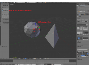
Step 1: Grab the Destination
Open the "Align Lines" tool in the Tools Panel (T) in the 3D View. Then, in edit mode, select the two vertices of your "destination" edge on the icosphere and hit the "Grab Destination" button. This is the "fixed" edge that we will move our selection to (in this case, our pyramid).
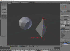
Step 2: Select the Source
Next, select the pyramid object (since this is the object we want to move), and in edit mode, select the two vertices of your "source" edge. Just leave these vertices selected. When the pyramid object is moved, this edge will be aligned to the "destination" edge we grabbed earlier.
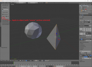
Step 3: Apply
In object or edit mode, under "Apply to:" hit the "Object" button. Your result should look similar to the second image below (it may differ slightly depending on what order you selected the vertices in):
A (Slightly) More Complex Example
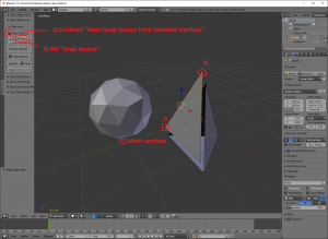
Let's say that instead of moving an entire object, we want to move *part* of a mesh while we're modelling. We'll use the same shapes (almost) as the previous example, so setup is similar and step 1 is the same. Here's a before/after image:
Step 2: Select the Source (Continued from step 1 above)
Select the pyramid object, and in edit mode, select the two vertices of your "source" edge. Uncheck "Auto Grab Source from Selected Vertices", and hit "Grab Source" (this will manually grab the source from the currently selected vertices now).
Step 3: Select the Mesh Part You Want to Move
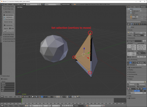
On your pyramid, select only the floating face (You can either do it manually, or Deselect All (A) and, with your mouse hovering over a corner of the floating face, Select Linked (L)...Invert Selection (ctrl + I) may be helpful here also).
Step 4: Apply
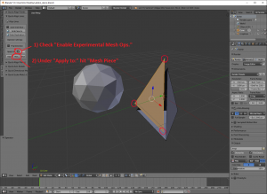
First, check "Enable Experimental Mesh Ops." (currently, the addon does not support operations on objects with non-uniform scaling, so this step is a precaution to warn you of that). Then, in object or edit mode, under "Apply to:" hit the "Mesh Piece" button. Your result should look similar to the second image below (again, it may differ slightly depending on what order you selected the vertices in):
Advanced Tools
The Advanced Tools offer more options and features than the Quick Tools, so they generally require more setup and have slightly different usage patterns (they also allow you to use imaginary geometry). For every Quick Tool, there's an advanced counterpart that offers more control. You can access the Advanced Tools in the Properties Editor > Scene context.
The Advanced Tools allow you to freely track (and optionally save/reuse) as many pieces of geometry as you like in one centralized list. Every point, line and plane you grab to create new transformations will be listed here. You can also save multiple variations of the same transformation (these will also be saved to the list, just like your geometry items).
The upper section of the panel lets you add and configure new geometry and transformation items, while the lower section lets you edit the current item (it will change depending on what item you currently have selected).
A Basic Example, Using Imaginary Geometry
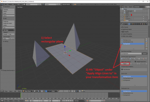
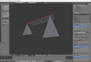
For this example, we will align one edge of a rectangular plane with an imaginary edge formed by the tips of two separate pyramid objects. Here's a before and after image to illustrate the setup and the results:
Step 1: Grab the Source
First, click the "Add New Line" button (looks like a blue arrow) to start tracking a new line. This is basically a "blank", unconfigured item. Then, in edit mode, select the two edge verts of the rectangular plane and hit "Grab All Global" on your new line item to quickly and easily auto-grab the start and end coordinates of your source line.
Optionally, rename this item "My Source Line" if you want, under "Item Name and Type" so that it's easier to identify in the list later.
Step 2: Grab the Destination
Since our destination line is actually an imaginary line running between the two pyramid peaks, we will manually grab the start and end points of the destination line.
Click the "Add New Line" button to start tracking your new destination line (as in the last step).
In edit mode, select the first pyramid's peak vertex (the line's starting point), and in your new line item, under "Start:" and "Grab:", click the lone globe icon (it's the third of three icons at the upper right of the point's coordinates, called "Grab Global Coordinates"). Then, select the second pyramid's peak vertex (the line's end point), and under "End:" and "Grab:", as we did before, click the "Grab Global Coordinates" button.
Optionally, rename this item "My Destination Line" if you want, under "Item Name and Type" so that it's easier to identify in the list later.
Step 3: Configure the transformation
Now that our target lines have been set up, we can configure an alignment operation that refers to both of them. Click the "Add New Transformation" button (it looks like a red, green and blue transform manipulator). You'll notice that it shows up in the list, next to the lines you made earlier. Then, under "Transformation Type:", click "Align Lines". Again, as above, this is basically a "blank", unconfigured transformation.
In the "Source Line" list near the bottom of the transformation item, click to highlight the "source" edge we grabbed in step 1. In the "Destination Line" list, click to highlight the "destination" edge we grabbed in step 2.
Optionally, rename this item "My Alignment" if you want, under "Item Name and Type" so that it's easier to identify in the list later.
Step 4: Apply
Select your rectangular plane, and (in object or edit mode) under "Apply Align Lines To:" on your transformation item, hit "Object". Your result should look similar to the second image below:
Some thoughts
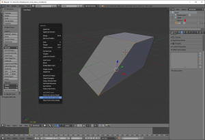
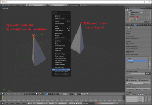
A) There's a shortcut for quickly auto adding and grabbing coordinates for new Point, Line and Plane items. In the 3D View, in edit mode, select up to 3 points for your Point, Line or Plane, and hit W > Point from Active Global (or Line or Plane from Active Global).
B) Once you apply your transformation, it will stick around in case you want to reuse it or apply it to a different object. In that case, your object/mesh piece will be transformed as if a ghost of the original geometry were still there. This can be useful for maintaining the relative positioning (or relative offsetting) of separate objects/mesh pieces. If you don't want to save an item after you're done with it, you can delete it from the list with the X button at the right side of the list.
C) If you move parts around during setup, your transformation will no longer work as expected. This is a (desired) side effect of how coordinates are stored. An option to save and track actual mesh vertices may be added later, if enough interest is expressed in this.
D) You can compose a Plane or Line (or Point) using a variety of methods. You can grab coordinates from the 3D cursor, an active vertex, or type coordinates in directly for each corner of a Plane item, for instance. There will be more support for measuring lengths, angles and directions in future updates.
Measuring Quantities and Composing New Items
By using "Calculation" items in the Advanced Tools, you can calculate the length of a line, the distance between points, the normal of a plane, and more. Calculation items work by comparing Point, Line and Plane items that you save in the Advanced Tools list. Some Calculations give you a number (like Line Length), while others create new geometry items that will show up in the Advanced Tools list alongside your other saved geometry items.
Some Calculations only involve one item (like line length), while others involve multiple items (like distance between points). You can toggle between these categories with the "Single Item" and "Multi-Item" buttons in your Calculation item under "Calculation Type:". For either category, just highlight the item(s) you're interested in in the "Targets:" list(s), and all of the available Calculations for those type(s) will be listed below under "Available Calc.'s and Result".
See "Available Calculations" below for a full list of the available Calculation operations.
Getting the Distance Between Two Points
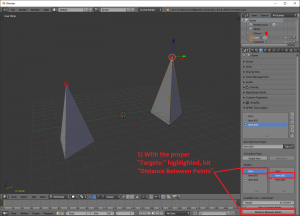
To illustrate basic usage for Calculation items, we will calculate the distance between two points. You should already have two points saved in the Advanced Tools list (if not, in edit mode, select a random vertex and hit W > Point from Active Global, once for each point, and make sure to use a different vertex for both).
Click the "Add New Calculation" button. Make sure "Multi-Item" is toggled (it's the default).
Under "Targets:", highlight the first Point item as the first target (the lefthand list), and highlight the second Point as the second target (the righthand list). Now, hit "Distance Between Points" to calculate the result, which will show up in the "Result" field under your targets.
Shifting An Axis of Rotation
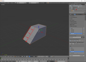
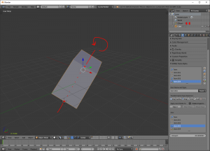
For this example, we're going to choose an edge from the pictured wedge object (see below) as an axis, shift that axis over to the center of the inclined face, and rotate around it. Note: the center line doesn't actually exist on the mesh, and we could also choose, for instance, 1/3rd or 1/5th of the way from the left edge, so try to imagine other creative uses for your calculations/transformations. Before/After:
Step 1: Grab the Axis
In edit mode, select the two axis vertices, and hit W > Line from Active Global (you'll see this line show up in the Advanced Tools list).
Step 2: Shift the Axis
Now we need to grab the new location for our axis (starting in the center of the inclined face, instead of on the left edge). Select the bottom edge vertices of the inclined face, and hit Shift + S > Cursor to Selected.
Hit the "Add New Point" button to track a new Point. In your new Point item, hit "Grab Cursor". This is the location where the axis will be shifted to.
Hit the "Add New Calculation" button to add a new Calculation item. Highlight the Point item as the first target, and the Line item as the second target (or vice versa, for this operation it doesn't matter which one is first). Then, hit "New Line at Point". The new, shifted axis will appear as a Line item in the Advanced Tools list. Rename the line "fancy new line" if you want to (optional).
Step 3: Apply the Axis Rotation
Hit the "Add New Transformation" button, then hit "Axis Rotate" under "Transformation Type Selectors" to select the operation. For "Axis", highlight the newly created Line item from earlier, and type 45 for the "Amount". To apply the transformation, select your wedge object in the 3D View, and under "Apply Axis Rotate to:" hit "Object". Your result should look like the second image below:
Reference Manual
Available Transformations
Align Points
Matches the location of "Source Point" to a "Destination Point". Before/After:
Transformation Modifiers
- Set Length Equal to One:
Move the source toward the destination by 1 unit (instead of the actual distance). This can be used in conjunction with the "Multiplier" option to move a specific numeric amount (check this and using a multiplier of 2.4 will move the source 2.4 units in the direction of the destination).
- Flip Direction:
Moves the source away from the the destination, rather than toward it.
- Multiplier:
Multiplies the length of the move. Can be used to double the move distance, for instance, or if used with the "Set Length Equal to One" option, to move a specific numeric amount (check "Set Length Equal to One" and use a multiplier of 2.4 to move the source 2.4 units in the direction of the destination).
Align Lines
Aligns a "Source Line" with a "Destination Line" so that the source points in the same direction as the destination, and the "Start" point of the source line is at the same location as the "Start" point of the destination line (making them collinear). Before/After:
Transformation Modifiers
- Flip Direction:
Flips the "Start" and "End" points of the "Source Line", so that when aligned, the source points in the opposite direction instead of the same direction as the destination.
Align Planes
Moves and aligns a "Source Plane" so that it sits flat against a "Destination Plane" (making them coplanar). Before/After:
Transformation Modifiers
- Flip Direction:
Flips the direction of the "Source Plane" normal, so that when aligned, the source plane's normal points in the opposite direction instead of the same direction as the destination's normal.
Directional Slide
Moves a target in the direction of a supplied line. Before/After:
Transformation Modifiers
- Set Length Equal to One:
Move the target in the specified direction by 1 unit (instead of the supplied line's actual length). This can be used in conjunction with the "Multiplier" option to move a specific numeric amount (check this and using a multiplier of 2.4 will move the target 2.4 units in the direction of the supplied line).
- Flip Direction:
Moves the target in the direction opposite the supplied line, rather than in the same direction as the supplied line.
- Multiplier:
Multiplies the length of the move. Can be used to double the move distance, for instance, or if used with the "Set Length Equal to One" option, to move a specific numeric amount (check "Set Length Equal to One" and use a multiplier of 2.4 to move the target 2.4 units in the direction of the supplied line).
Scale Match Edge
Scales a target so that the "Source Edge" length matches the "Destination Edge" length. Before/After:
Axis Rotate
Rotates a target around the supplied "Axis" line by the specified "Amount". The "Amount" is either degrees or radians, as specified by the user in Blender's Properties Editor > Scene Context > Units panel. Before/After:
Available Calculations
New Line from Point (Single Point)
Calculation Type: Single Item
Input: Point
Output: New Line item (shows in the Advanced Tools list)
Useful for turning a Point into a Line from the origin. Creates a new Line item with the "Line Start" equal to the world origin (0, 0, 0), and the "Line End" equal to the Point's coordinates.
Line Length (Single Line)
Calculation Type: Single Item
Input: Line
Output: Number (shows in the "Result" field)
Gives the length of the highlighted Line item, shows up in the "Result" field.
New Line from Origin (Single Line)
Calculation Type: Single Item
Input: Line
Output: New Line item (shows in the Advanced Tools list)
Moves the current line from its original starting location to the world origin (direction and magnitude remain the same).
Get Plane Normal (Normalized), (Single Plane)
Calculation Type: Single Item
Input: Plane
Output: New Line item (shows in the Advanced Tools list)
Calculates the normal of the current Plane item, with the resulting length set to 1 (normalized).
Distance Between Points (Point + Point)
Calculation Type: Multi-Item
Input: Point + Point
Output: Number (shows in the "Result" field)
Gives the distance between the highlighted Point items, shows up in the "Result" field.
New Line from Points (Point + Point)
Calculation Type: Multi-Item
Input: Point + Point
Output: New Line item (shows in the Advanced Tools list)
Useful for creating a line from two points. Creates a new Line item, with the "Line Start" equal to the first target, and the "Line End" equal to the second target.
New Line at Point (Point + Line)
Calculation Type: Multi-Item
Input: Point + Line
Output: New Line item (shows in the Advanced Tools list)
Useful for moving a line to a new location (shifting an axis of rotation, for instance). Creates a new Line item, with the "Line Start" equal to the Point location, but with the magnitude and direction equal to the Line item's.
Add Lines (Line + Line)
Calculation Type: Multi-Item
Input: Line + Line
Output: New Line item (shows in the Advanced Tools list)
Creates a new Line item by performing vector addition of the two Line item targets.
Subtract Lines (Line + Line)
Calculation Type: Multi-Item
Input: Line + Line
Output: New Line item (shows in the Advanced Tools list)
Creates a new Line item by performing vector subtraction of the two Line item targets (first line minus second line).
Contact
You can email me directly at egtwobits@gmail.com for feedback, bugs, or requests (nothing is promised!). It'd be great if you would put "Mesh Align Plus (FEEDBACK|BUG|REQUEST):" in your subject line.

