Extensions:2.6/Py/Scripts/NeuroMorph/3D Drawing
| UI location | View3D » 3D Drawing | ||
|---|---|---|---|
| Version | 1.0.0 | Author(s) | Anne Jorstad, Biagio Nigro, Corrado Cali, Tom Boissonnet |
| Blender | 2.78 | License | GPL |
| File name | NeuroMorph_3D_Drawing.py |
|---|---|
| Current version download | https://github.com/NeuroMorph-EPFL/NeuroMorph/tree/master/NeuroMorph_3D_Drawing |
目次
NeuroMorph Links
Blender Wiki Home
Code on GitHub
For more information please visit the NeuroMorph project website.
Overview
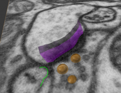
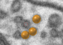
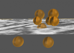
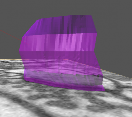
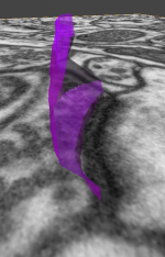
The 3D Drawing module allows the user to scroll through images stacks in all 3 dimensions, place spherical markers (vesicles) on images in 3D, and draw lines on images that can be constructed into both open surfaces (synapses) and closed surfaces (mitochondria) in 3D. Open surfaces with holes are handled.
Retrieve Object from Image: An additional tool to aid in scene exploration and connectivity analysis when there are many hidden objects in the scene.
3D Drawing: Description
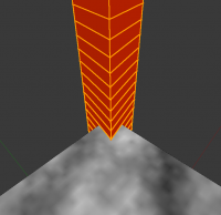
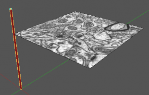
This tool allows the user to load, scroll through, and draw on images in 3D image stacks. A standard image stack (images in the X-Y plane are stacked in the Z dimension) must always be loaded; X- and Y- stacks can optionally also be used. The tool will create a red Image Stack Ladder, which is a column the height of the image stack, with a vertex in the ladder for every image plane. This object allows the user to navigate through the images by clicking on any vertex and displaying the image at that point. Once an image is loaded, the stack can be scrolled through with the mouse scroll wheel.
Display Images from Stack
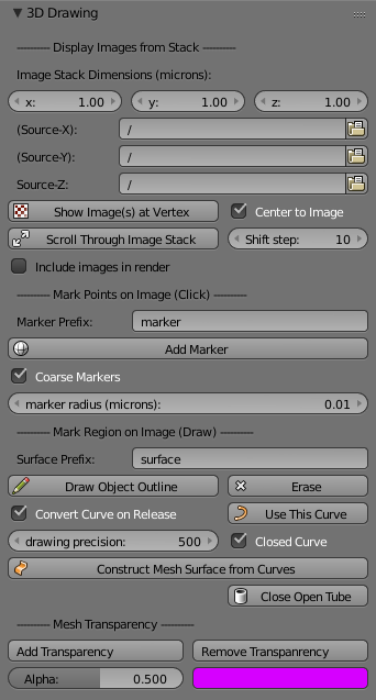
- Image Stack Dimensions (microns): The x-, y-, and z-dimensions of the original image stack used to obtain the mesh objects, in microns. (Must be consistent with the imported meshes, else the images will display incorrectly.)
- Source Z: Click to navigate to the folder containing the images of the original image stack (the Z-dimension).
- Optionally, also add image stacks in the X- and Y- dimensions, to be able to visualize images in all 3 dimensions.
- The X and Y image stacks can be generated using the Fiji macro Generate_3D_image_stacks.ijm provided on our GitHub page.
- Show Image at Vertex: Displays image plane(s) from stack at the location of highlighted mesh point (in Edit mode), either from the Image Stack Ladder or from any scene object. Can display multiple images at once. (It is not recommended to click this button with more than just a few highlighted points.)
- Check the Center to Image box to center the view to the new image.
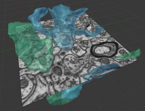
- Scroll Through Image Stack: From an active image, use the mouse scroll wheel to scroll through the image stack and have the images displayed at their proper locations superimposed on the mesh objects. (Shortcut: CtrlY)
- Can add markers, draw and erase on images from scroll mode.
- Optionally scroll through the image stack faster by pressing shift while scrolling, moving the image by the shift step instead of 1.
- Include images in render: Must be checked to have images rendered as visible textured planes in an animation.
Mark Points on Image (single click)
- Marker Prefix: Default name given to spherical marker objects.
- Add Marker: Add a spherical marker to the scene at the cursor location on the selected image.
- Adjust radius by setting marker radius (microns).
- Shortcut: AltM, works from scroll mode.
- Coarse Markers: Create coarse marker spheres with fewer vertices, keep this checked when using scenes with many markers.
Draw Curves and Surfaces on Image (free draw)
- Surface Prefix: Default name given to surface objects.
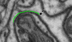
- Draw Object Outline: Draw curve on image surface using Blender's grease pencil.
- Shortcut: CtrlD
- From scroll mode both CtrlD and simply D will work.
- Erase part of the curve if necessary and continue to draw to achieve the desired curve.
- Shortcut: CtrlE
- From scroll mode both CtrlE and simply E will work.
- Use This Curve: Once you are satisfied with the drawn curve, click to convert drawn curve to Blender mesh object curve.
- Shortcut: Ctrl⇧ ShiftD
- Convert Curve on Release: For faster annotations, check this box to convert drawn curve to mesh curve immediately on mouse release.
- Drawing Precision: Adjust number of points to use when creating curves and surfaces (points per image length, eg 500).
- Closed Curve: Check this box if you are drawing closed tube-like surfaces. Note that this add-on cannot handle branching.
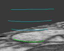
- Construct Mesh Surface from Curves: Select several mesh curves, then click to combine them into a single smooth mesh surface. For a smoother surface, use more individual curves.
Surfaces with Holes
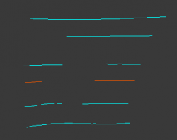
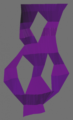
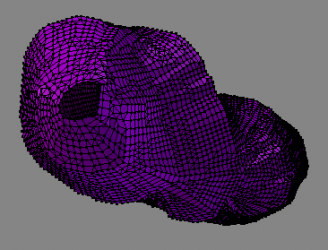
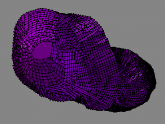
- The 2D surface construction tool is able to handle any number of holes in the surface mesh.
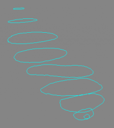
- To "draw" a hole, simply draw the surface curves that are on either side of the hole, leaving a gap where the hole should be. Both sides of the hole must be drawn on the same image slice (see red curves on the right), otherwise the tool will not recognize the two curves as being on either side of a single hole.
- Select all curves and click 'Construct Mesh Surface from Curves' as before.
Closed Surfaces (Tubes)
- It is also possible to draw and construct closed tubular surfaces. Check the Closed Curve check box before drawing.
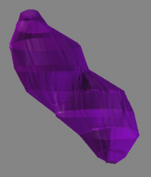
- After a tubular mesh surface is constructed from its curves, the ends of the tube will be open. To close off these ends, for example to construct a mitochondria, click Close Open Tube.
- The tool cannot handle branching tubes at this time.
Mesh Transparency
- Add Transparency: Define transparency and color of selected object. Provides alpha (transparency) and color boxes for user input.
- Delete Transparency: Removes transparency of selected object.
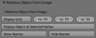
Retrieve Object from Image: Description
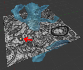
Users can select a grid point on an image and make visible any scene objects that exist around that point that are currently hidden.
- Display Grid: Overlays a grid of nx by ny points on the active image. (For images from the X or Y image stacks, nz is also used.)
- Display Object at Selected Vertex: Makes visible all objects that contain the currently selected grid point(s) (in Edit mode). If objects are stored in separate layers, they will be made visible in their respective layers. (It is not recommended to click this button with the entire grid highlighted.)
- Show Names: Displays the names of currently selected objects in the scene and their child objects.
- Hide Names: Hides the names of currently selected objects in the scene and their child objects.
