利用者:ReD Fox/BevelToolDev
目次
Summary
Blender's edit-mode bevel tool will be completely recoded to include the following features:
- Works only on selected geometry
- Properly handles selection modes (vert/edge/face)
- Can use either per-vertex or per-edge beveling methods
- Bevel amount can be specified either as a radius or a distance
- Bevel resolution can be set to an arbitrary value
- Allows numeric input and value constraints
- Bevels both face and edge (wire) geometry
- Works with f-gons/n-gons
- Works intelligently with UV's, vertex groups, vertex colors, etc.
- A real-time, actual-data preview
Code-wise, the tool will be implemented with the following characteristics:
- Will use the BMesh API
- The core functions will be shared between the edit-mode tool and the modifier stack
Details and Explanations
Beveling and selection states
When considering which geometry to bevel, the tool will first perform several checks on the selection states and selection modes of the geometry.
Currently, Blender supports three different methods of selecting geometry. These are termed the vertex, edge, and face selection modes, appropriately. For the purpose of the bevel tool, however, the only key difference between them will be found in the vertex selection mode, since the face and edge selection modes are practically equivalent for both edge and vertex-based beveling (selecting a face would be equivalent to selecting all of its bordering edges).
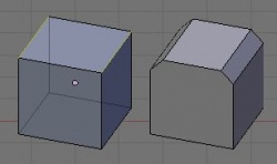
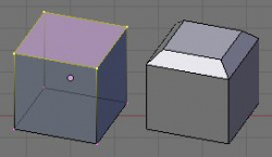
Figure 1 shows an example of the bevel being limited by the edge selection mode. Figure 2 shows the "equivalent" selection in vertex selection mode. Note that everything bounded by the selected vertices is also selected. This implementation is a bit different from other modelers that support selection modes (such as Wings) in that the vertex selection mode does not necessarily imply a vertex bevel, although it may default to a vertex bevel if a vertex is selected in isolation (see edged-based vs. vertex-based beveling below).
Edge-based vs. vertex-based beveling
Figure 3 demonstrates the difference between the vertex-based beveling method and the edge-based method. Basically, the vertex method bevels the corner without affecting the connected edges, whereas the edge-based beveling method is the more common, intuitive method that bevels all along the associated edge.
The edge-based method will be the default for all selection modes, although a method of switching between edge and vertex beveling will be implemented. It will likely utilize a special key, or perhaps the middle mouse button, as a toggle after the tool has been invoked. However, for vertices that are selected in isolation (i.e. vertices that are selected but do not share an edge with another selected vertex), the vertex-based beveling method will be used. This means that there are cases when both methods may apply to a mesh at the same time.
Bevel values and numeric input
There are three major ways to specify the value of a bevel: a distance, a radius, or a percentage. The bevel-by-percentage, which is basically a distance that varies based on individual edge lengths, will not be implemented for this tool. Figure 4 illustrates the difference between specifying a bevel by distance (bevel amount), or by radius. For a 90 degree angle, these are equal. However, for an angle greater than 90 degrees, the bevel distance becomes smaller than the bevel radius. Similarly (though it is not shown in the diagram), if the angle is less than 90 degrees, the distance will become larger than the radius. The bevel-by-distance (as opposed to the bevel-by-radius) is a more general purpose method, and, thus, will be used as the default. A method for allowing the user to toggle between the two methods will be implemented.
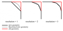
Since this is a mesh tool, the beveled geometry must be approximated using face segments. This tool will allow an arbitrary number of face segments to be specified (unlike the previous bevel tool in Blender, which would only allow segments to be created as powers of 2). Figure 5 shows an example of this.
All of these options (toggling between vertex and edge-based beveling, specifying the bevel amount, defining whether it is by-radius or by-distance, and specifying the bevel resolution) will be interactively available to the user while the tool is in progress, much like many of the current transform tools (grab, scale, rotate, etc.) already in Blender. Also, the CTRL and SHIFT keys will function as constraints, affecting the bevel amount in a similar manner to how they constrain current transform operations (CTRL "snaps" to certain increments, and SHIFT increases precision).
Beveling and affected geometry
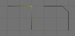
The current bevel tool in Blender only considers face geometry. The new tool will also consider pure-edge geometry (wire loops). An example of such functionality is shown in figure 6. It will be limited to manifold conditions, though, so an edge shared by more than two faces (in the case of face geometry) or a vertex shared by more than two wire edges (in the case of pure edge geometry) will not be beveled.
Additionally, great care will be taken to ensure that other geometry-related data, such as UV's, vertex groups, vertex colors, and so on, will be handled according to determined rules. Much of this will be handled by the BMesh API, but there are several details that this tool will need to manage.
Also, great care will be taken to ensure that faces with advanced geometric requirements, such as f-gons or n-gons, will be handled intelligently.
Real-time, actual-data preview
The current bevel tool in Blender utilizes a rough preview with wire outlines. It is my desire that the new bevel tool display the actual data as the user adjusts the bevel amount and other options. The exact method for accomplishing this has not been determined at this time, but several methods have been suggested to me.
Examples
- proper face inset
- corners (poles) with adjacent edge bevel and higher resolutions
- non-manifold geometry (it's ignored)
- correct/incorrect comparisons
- explanations
- expected/unexpected behavior (non-manifold)
- case scenarios (only edges, strange geometry, etc.)
Algorithms
- diagrams
- explanations
- confusions, difficulties, comparisons, etc.
Questions/problems
- How should bevel distance limits - i.e. the bevel amount is greater than the length of one of the edges - be handled? Should it limit the bevel amount for the entire tool, or just the geometry associated with that edge? (This may be a problem mainly for the vertex bevel, and may be related to the self intersection problem below.)
- Should face inset detect self intersections? If so, to what degree and how should they be handled? Should it limit the bevel amount for the entire tool at the intersection point, limit the bevel amount only for the offending face, or actually produce intersected geometry?
- An "edge extrude" option was mentioned as being useful. Such an option would use the bevel algorithms, and would be relatively simple to add. Should it be incorporated (perhaps as resolution = 0) into the bevel tool?
- Should a bevel-by-percentage option be implemented?


