Doc:2.6/Manual/Render/Camera/Perspective
Page status (reviewing guidelines)
Copy
This page is a copy of the same page in 2.4 manual, need to be updated
|
Perspective in Render
When you press F12 and get your render, you see an image as seen through the camera's "perspective". Like how you can view your model in 3D View from the top, front, side, or user perspective, you can render your object from different perspectives. This perspective takes into account the lens size, type, and offset in giving you that picture. Each perspective uses a different number of vanishing points.
If you look at a 3D image of a cube, you will see three kinds of edges: vertical, horizontal, and depth. If all of the vertical edges are exactly parallel, there is no vanishing point for them. If however, they are not parallel, if you extended them by continuing them with a ruler, they would at some point intersect. That point is called the vanishing point.
For special purposes, different kinds of render cameras can be set up to give you different perspectives. For reasons discussed below, you may wish to limit the number of vanishing points, especially for architectural purposes. Architects and drafting people are responsible for rendering the object or building with true dimensions and true relative proportions.
If you look at that example render, the building looks all sorts of distorted, like it had been made of mud and was collapsing. If you told a builder to build that, you would end up with a building that actually had leaning walls and rooms that were narrower at the top.
Way back in the old Greek days, when they started building tall columns, they built them thicker at the top than at the bottom, so that when viewed looking up, the two sides would look straight up and down. Then they even started narrowing the columns at the top to give the illusion that the building was taller and would look higher. During the Renaissance, the concept of using vanishing points in art evolved. Blender offers a few tricks of its own to let you do the same.
Note
To follow sections below you will need to know how to adjust Camera Settings
|
Three Point Rendering
When looking at or rendering a picture of a high building from ground level off to one side, and aiming up, using the normal 35mm camera, you get 3 point perspective. If you laid a ruler along the vertical lines, you would see that they converge to a point above the building.
The horizontal lines are converging off to one side (the left in this example), and depth (receding) lines are converging to a different third point (somewhere off to the lower right in this example). Hence the name 3-point rendering - there are three vanishing points.
This is reality, and there is nothing wrong with that. When you next step outside and look at a tall building, this is what you actually see. However, your mind knows that the building is square, and can adjust your perception of the building so that you are not scared that the building is going to fall over.
Two Point Rendering
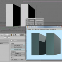
Normal architectural rendering is called two point rendering; when vertical lines are parallel, and horizontals, if followed out to the side, converge on one point, and receding or depth lines converge to a second point.
Architects often like this Two-Point rendering, so that the sides of their buildings are completely vertical and don't appear to be falling inward. This is also quite nice for compositions and schematics, given that the lines of the paper you print on and the screen you view with are also straight.
Previously to get a 2-point perspective, you had to aim the camera level to the horizon, however this resulted in the top half of the building being cut off and the horizon being in the exact middle, which looks very boring. Architectural photographers use 'shift lenses' to solve this problem. Shift lenses shift the image to another place on the film.
This technique works well for high buildings as well as for normal sized objects.
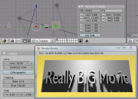
Most of the time, the two vanishing points are horizontal and depth lines, with the vertical lines parallel. However, some titles are done with the horizontal lines parallel, and the vertical and depth lines having the vanishing point. This dramatizes and exaggerates the massiveness and height of the title.
To get this effect, position the camera at ground level, centered, angle the camera upward, and shift the render passpartout down. In the example, the camera is rotated 30 degrees upward, at ground level with the title. A bright key light with a short falloff provides dramatic lighting that is bright in the middle and falls off toward the sides, further enhancing the depth.
To achieve 2-point rendering:
- Use a short wide angle lens camera, say with a Lens Size of 10 mm placed close to the building, or a long lens farther away from the building. These differences affect the depth of the building render, with longer lenses making the building appear thinner and less dramatic or distorted. The example uses a 40mm lens.
- Position the camera off to one side of the object, vertically halfway up the building to minimize distortion of the vertical building edges. You may alter this vertical (Z value) position to be slightly higher than ground level or higher than the top (if you want to see the top of the object or building). To show the front bottom corner of the building jutting out, raise up the camera.
- Angle the camera to be looking away from the building and directly level at the horizon - not pointed up or down (note the 20 degree Z angle in the example). This should make the vertical lines parallel. The more the camera looks at the object, the closer the vanishing point for the horizontal lines, and perceived depth will increase as that vanishing point gets closer as well.
- You may have to angle the camera slightly down (just 1 degree or so) so that vertical lines appear vertically up and down, both near and far. If the lines are curved, use a longer lens. With your 3D View set to Camera view, use the passpartout or pixels on your monitor to determine vertical.
- Move the camera toward/away from the object until it appears near a corner of the render and is the right size.
- Adjust the Shift: X and Y settings until your object is positioned properly.
One Point Rendering
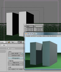
One point rendering is where vertical and horizonal lines are parallel, and depth lines converge at one point. Architects really like these renders, since the front-facing faces are true and square, and the building recedes off into the distance so that it looks like it has some depth.
If the camera is placed at ground level, even with the bottom of the building, it really looks dramatic but orderly in a weird sort of way. Title graphics are sometimes rendered this way.
To get 1-point (1pt) renders
- To get more dramatic depth lines, use a short wide angle lens camera, say with a Lens Size of 10 mm, very close to the building. For a more normal appearance, stick with the 35mm lens.
- Position the camera off to one side of the object, slightly higher than the top (if you want to see the top of the object) or at ground level (the example image has the camera almost at ground level). If you position the camera below ground level, the bottom depth lines and horizontal lines will merge up (become congruent) for a very dramatic effect.
- Angle the camera looking straight back, perpendicular to the true face. Vertical lines should be parallel. Rotate the camera on the Z axis slightly toward the object until the horizontal edges are also parallel. Technically, you are correcting for parallax (just a casual line to drop on your girlfriend to impress her). The example has the camera rotated 0.5 degrees toward the object.
- Move the camera toward/away from the object until it appears at the proper size relative to your passpartout.
- Adjust the Shift: Y settings until the bottom of the passpartout (or title line if you want to show some approach ground in front of the building) is even with the bottom of the building. Adjust the X setting until the building is centered (or slightly offset from center for artistic appeal, or to show the parking lot next to it) as shown.
In the example screenshot, the Lens is 35, X is negative and Y is positive. The camera is off to the right of the object, even with the bottom of the building. If X & Y were zero, the building would have appeared off camera, in the upper left-hand corner of the passpartout.
| Parallel Horizontal Edges | |
| You can use the lines of the passpartout as a guide in rotating the camera to determine when the horizontal edges are parallel. |
Orthographic Rendering
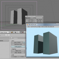
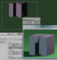
Zero point rendering is where vertical, horizontal AND depth lines are all parallel, and is commonly rendered at 45 degree, 30 degree, or 60 degree angles. With all of those sets of edges parallel to each other within that set, there are no vanishing points.
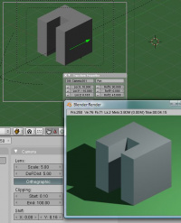
The example shows that same building rendered at 45 degrees from all angles. Note that the vertical lines are parallel to each other, the horizontals, and the depth lines are parallel to each other. From this, it is very easy to see that the left top edge of the building is the same length as the right top edge, and that the building is as deep as it is wide and high; if you measured the edges with a ruler, they would all be the same.
Orthographic rendering gives a true mathematical render of the shape of the object. An Orthographic perspective is what you see in the User View of a 3D window (if View->Orthographic is turned on).
To get an Orthographic render:
- Enable Orthographic in the Camera panel. This makes at least one face to be true to the camera.
- Point the camera at the object
- Position the camera or alter the Scale so the object is the desired size
With Orthographic cameras though, Lens size is irrelevant, since light rays do not converge to the camera from a field of view. They come in parallel, and so you can only Scale the camera size to take in more or less of that huge plane.
Note that Shift X & Y are zero, and that the camera is positioned perfectly off at a 45 degree angle to the object/building, and is rotated exactly 45 degrees to face the building. Thus, the near edge is aligned with the back edge (since the object is square).
Orthographic renders are usually made at 30, 45, or 60 degree angles to the object. Specific measurements are left to reader using triangle math.
Isometric Rendering
While we are at it, we might as well cover Isometric rendering, which is a very specific type of orthographic render very often used in drafting and third-person computer games.
In Isometric renders, you want your depth lines and your horizontal lines to be at 30 degrees off horizontal, and your vertical lines to be, well, vertical. Some complicated vector calculus in Wikipedia gives us a convenient shortcut. To get Isometric Renders:
- Make your camera Orthographic
- Add a "Track To" constraint (Object F7 context, Constraints panel) to the camera for it to Track To the object (type the name in the Target OB: field), using To: -Z and Up Y.
- Position your camera so that it is 45 degrees in the XY plane from your object, and raised at a 30 degree angle. If your object is at XYZ (0,0,0), then your camera should be at (10, -10, 10), or for a view from the left side, (-10, -10, 10)
- Adjust the Scale of the camera (Editing F9 context, Camera panel) so that the object fits within the passpartout
- Adjust the Shift: Y value so that the object is centered in the render.
