利用者:Damiles
目次
Work in Progress
Sequencer
Supersampling
References
- http://www.americaswonderlands.com/digital_photo_interpolation.htm
- http://www.dpreview.com/learn/?/key=interpolation
- http://meesoft.logicnet.dk/Analyzer/help/help3.htm
- http://www.ornl.gov/sci/ismv/pdfs/publications/Price-FractalInterpolationOfImagesAndVolumes.pdf
Save/Load 3D properties view
Simple feature to save/load position of 3dView and layers. You can save a 3d view position and load in other 3dView
Video: http://www.artresnet.com/david/save_view.ogg
Patch: https://projects.blender.org/tracker/index.php?func=detail&aid=6742&group_id=9&atid=127
Levels/Histogram Node Composit
Introduction
Not all the render or images that goes to composite or postproduction has the color or gray levels correct. The best results are obtained by color correction under postproduction, and the best way to achieve it is with an histogram representation of the image, with the Red, Green, Blue components, and the Luminance component (component Y of an YUV representation).
Project Goals
Solution
Resources
https://projects.blender.org/tracker/index.php?func=detail&aid=3984&group_id=9&atid=127
References
Motion Tracking
Aproved
Node Custom user Names
Node Blur Percent
Interpolations Algorithms
The "results" are scaled to show better the interpolation
Nearest pixel interpolation
This is the simplest and fastest way to calculate the value of pixel. This consists in getting the nearest pixel corresponding to the original image.
If the result of inverse function get the pixel (0.3,0) then we get the value (0,0), and if we get the pixel (0.7,0) we get the value of pixel (1,0).
This is the fastest algorithm but it makes a pixeled image.
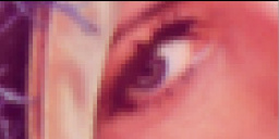
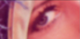
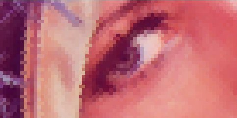
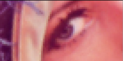
Original:
Result:
Bilinear pixel interpolation
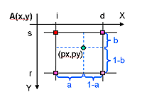
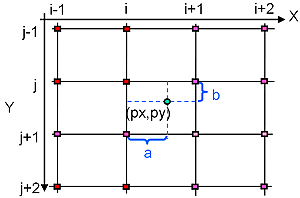
This method of interpolation consists in tracing a line between the low and high rounded value of returned inverse function and calculate the resultant value with the line function.
The formula:
A’(px, py) = (1-a)(1-b)A(s, i) + a(1-b)A(s, d) +(1-a)bA(r, i) + abA(r, d)
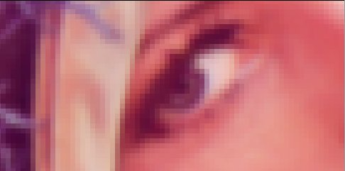
Original:
Result:
Bicubic pixel interpolation
This method produces the better result but is the slowest algorithm. It calcules the value with a cubic curve with the 4 neighbour pixels.
The formula:
Original:
Result:
Transform Sequencer
- On Blender since 2.43
- A video sample:
http://www.artresnet.com/david/transform_01.mov
- A blend file example:
https://projects.blender.org/tracker/download.php/9/127/4992/2694/example.zip
Rotate Node Composit
Introduction
Rotate an image. Since 2.43, Thanks Ton.
Gamma Node
Since 2.44
Bright/Contrast Node
Since 2.44
Rejected
Bezier Mask Node Compositor
Introduction
The purpose of "Bezier Mask Node Compositor" is to provide the artist a tool that can draw a bezier over image to select an area to show and exclude the rest of image area.
The artist will be able select a value of feather to make smooth edges.
Artists needs
- Create a custom mask with closed curves
- Animate the curve nodes
- Select in/out of curve for define mask
- Select the smooth of border curve
- View the corresponding frame
- Be able to select different mask modes: normal, invert, intersect, in order to combine masks to create more complex effects.
Project Goals
Make a new composite node that implements an easy tool to create a beizer mask as implemented in cinelerra compositor.
The tool can do:
- Control points of beizer
- Image preview
- Animate the control points
- Edit the beizer control points
- Zoom and drag the area to better control interface.
- Define smooth edge.
- Get image correponding to frame
The result of node is an alpha image.
Proposed solution
Solution
(added by Ton) There's a couple of complex design decisions involved here
1) the Image Window is getting overloaded with options already... i received complaints about this already by the maintainers of that code. I do agree this bezier editing belongs there, but it won't make our code nicer :)
2) This option will mean that the image window will get a new kind of "mode" showing the active node in a composite. That's doable, but has to be looked at carefully. Probably it then should just show each node. Also a histogram node could be shown there for example. It also makes the compositor more complex; it should store in node the image as used by image window
3) You will have to add bezier editing in the image window. There's plenty of code for it already in blender, but all tied to 3d mostly... this can easily become a mess too, so would be nice if it can be done with maximum overlap and re-use of existing code.
4) The bezier curve ListBase itself should be stored in the Mask node, which isn't supported well yet, but can be coded. takes some design here too.
Big problem = how animation and keying then will go...
Might be idea to not store curve in Node, but link it to a Curve data block. that way the same curve can edited and Shape-key animated in 3d window OR; optionally store Object pointer even, and have the mask draw in ImageWindow based on projection with active camera, that way also object anim works, and camera motion, and so forth.
5) We need new code in Blender to render out such masks with 'soft' options.
First Version
To make a bezier mask:
1) In a 3D window, select the top view.
2) Set a background Image (if you need an image sequence, select a texture containing it). Set the background size to 5.
3) Make a bezier circle in the top 3D view. Rename it to something you can easily find/remember.
4) In the node compositor add Vector >> Bezier Mask.
5) Add a input image node and select the same image as the for the background.
6) Select the curve in node Bezier mask.
7) Set smooth if needed and set antialias. Default is smooth = 0 and antialias = 4.
8) Set in or out to use the inner or outer part of the bezier curve as the mask. It's like inverting the effect.
9) Connect the output of image to the input of the bezier mask node.
10) The Bezier Mask node has two outputs. Mask Only is a white/black mask, and Image with mask is the mask applied to the input image.
Note: you still need to have a Render Layers node if you have an animated curve.
Resources
References
Scale Node Compositor
Introduction
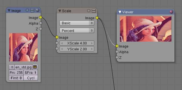
The scale node implements an image scaling through different modes: nearest pixel, bilinear, bicubic, and supersampling interpolation.
Project Goals
Implement new node to scale an input image.
- Implement fast solution, nearest pixel.
- Implement bilinear interpolation.
- Implement bicubic interpolation (ToDo)
- Implement supersampling interpolation.(ToDo)
- Option percent scale or pixel scale
Solution
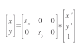
Scale function:
The new width and height:
where width' and height' are original width and height.
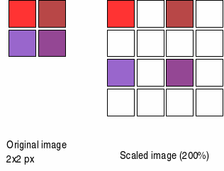
When we scale an image the result is:
We have a problem if we have the original image and scale, we leave blank pixels. Then we need make an interpolation algorithm.
Resources
Patch scale node of patchTracker
The result
Gain Node
A Color correction gain. It's rejected because you can do the same with other nodes.


