利用者:Intracube/Colour Management/Linear Workflow Issues
Note:
this page is work in progress.
|
目次
Colour management and linear workflow
Introduction
This page highlights some issues with colour correcting and grading using Blender's node compositor and also problems using Blender for motion graphics work.
Example of the problem
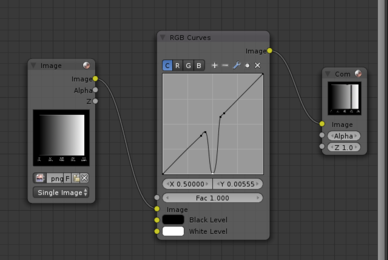
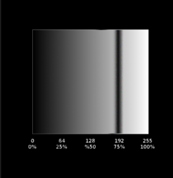
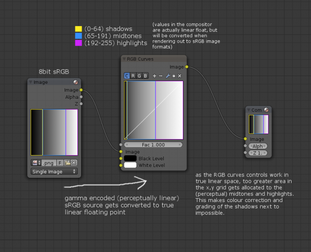
These images highlight some unusual behaviour with the compositor's RGB Curves node. The source image is a linear gradient, created and exported as a PNG from The GIMP. Notice how the notch position in the middle of the RGB Curves node isn't in the same position in the rendered output - it's shifted to the right.
Why is this happening?
Radiometrically linear vs perceptually linear
The behaviour can be put down to the difference between radiometrically linear (true linear) luminance values and perceptually linear (gamma corrected) luminance values. By default, Blender's internal pipeline works in a radiometrically linear space, whereas The GIMP, most 8bit image formats, common video formats, computer displays, SD and HD televisions, etc operate in a perceptually linear (gamma corrected) space – often sRGB for images and Rec.601 or Rec.709 for video.
Photometrically linear and gamma corrected work-flows each have their own advantages. For compositing photo-realistic renderings with multiple lighting passes, a radiometrically linear pipeline simplifies the process of combining lighting passes and ensures physically correct results which would otherwise be more complex to achieve using gamma encoded images.
For storing images or video (especially for formats with a relatively limited bit-depth like 8bit per channel - around 16.5M colours total), gamma encoding the values better allocates the available colours to match human perception. This means more colours in the shadows where human vision is sensitive and conversely less colours in the mid-tones and highlights. This technique reduces the visibility of banding/posterisation in darker areas of the image.
It's important to note that radiometrically equal steps in luminance do not correspond to subjective equal steps in brightness. Human visual perception of light intensity is not linear. To make a set of luminance values appear to have equal steps in brightness, they must be gamma encoded:
8bit image formats are almost always gamma encoded. Therefore, on a scale of 0 to 255, a value of 128 will appear roughly twice as bright as a value of 64. This is not the case with radiometrically linear values – a value of 0.5 will not appear twice as bright as a value of 0.25.
For the most part, Blender does the necessary conversions between linear and gamma encoded content so that imported images, video, rendered scenes and also UI elements like the Colour Picker look correct when viewed on a calibrated computer display. The settings to control this behaviour are in the Scene->Colour Management panel.
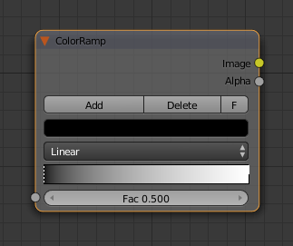
However there are a number of places where the linear to gamma encoded translation doesn't take place – such as the compositor's RGB Curves node 'grid' and the gradient editor of the ColorRamp node:
Looking back at the first image on this wiki page, the reason for the misalignment in the position of the RGB Curve 'notch' is because the RGB Curve node internally works in linear space but the image preview is then gamma encoded for display. There is therefore a mismatch which isn't being taken into account.
Why does this matter?
The primary use of RGB Curves in the compositor is as a visual tool for grading images. A user will typically add an RGB Curve node to their node tree and manipulate the curves while monitoring the output to get the desired result. The process of adjustment/feedback is iterative – the user will be 'eyeballing' the results.
This is in contrast to other nodes where the user would expect the adjustments to be radiometrically linear in nature – such as a straightforward exposure or gain control; which would be the equivalent of traditional ISO/ASA or f-stop adjustments. Math and vector nodes would also come under this latter category.
To recap, there are two key issues with the current RGB Curves;
- If a user has set the display device set to something other than 'None' - what appears as middle grey in the UV/Image Editor (render preview) won't be mapped to the literal middle of the Curves grid
- Most of the area of the grid is allocated to perceptual midtones and highlights. Virtually none of the area is mapped to the shadows. Shadows can be loosely defined as the bottom 25% of a perceptibly linear luminance scale. This makes adjustment of shadows using the Curves virtually impossible:
Although the RGB Curves node does have clipping and zoom options for the user to look at a smaller area of the grid, the controls are limited and aren't a solution.
What could be done
[todo]
