利用者:Pepribal/Ref/3DView/Header
目次
- 1 Header buttons
- 2 Mode selection button
- 3 Shade button
- 4 Pivot center buttons
- 5 3D manipulators and transform orientation buttons
- 6 Paint masking buttons
- 7 Layer buttons
- 8 Local/scene camera and layers button
- 9 Mesh select mode buttons (Ctrl⇆ Tab)
- 10 Particle select mode buttons
- 11 Limit selection to visible button
- 12 Proportional editing button (O)
- 13 Snap buttons (⇧ Shift⇆ Tab)
- 14 OpenGL render buttons
- 15 Copy/paste pose buttons
- 16 Pause button
Header buttons
The buttons available in the editor header will depend basicly on the current working mode. At the same time, the available modes depend on the type of the active object.
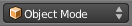 Mode selection button
This button, available in all modes, defines the current mode. These are the available modes, depending on object type:
- Object Mode is available for all object types.
- Edit Mode is available for mesh, curve, surface, metaball, text, armature and lattice objects.
- Sculpt Mode is only available for mesh objects.
- Vertex Paint is only available for mesh objects.
- Texture Paint is only available for mesh objects.
- Weight Paint is only available for mesh objects.
- Pose Mode is only available for armature objects.
- Particle Mode is only available for mesh objects with at least one particle system.
⇆ Tab switches between the current mode and edit mode. Ctrl⇆ Tab switches between the current mode and weight paint mode when the active object is a mesh, and between object mode and pose mode when the active object is an armature.
 Shade button
This select button is available in all modes. It lets us show the way objects will be drawn on the 3D viewport. These are the options available:
- Bounding Box shows wireframe cubes defining the objects bounds. The cubes are oriented in the local coordinates of the objects.
- Wireframe shows wireframe versions of the objects.
- Solid shows the surface of the objects shaded with a solid color, defined in the material Settings panel (Material context of the Properties editor).
- Texture shows one of the image textures of the object material (if applicable) mapped correspondingly onto the object surface. If the selected texture is not of image type, it will be drawn in solid mode. To select a specific texture, select its corresponding node in the Node Editor. The selected texture shows as a bluish node selector control in the Properties editor.
- Material shows the object surface with an OpenGL approximation of its material. The material is not fully rendered, as the aim of this mode is drawing speed. So if you want to see an accurate rendered view you should use rendered mode.
- Rendered shows the objects as they would be rendered. This mode gives a more accurate view, but is by far the slowest of all.
All these options use OpenGL render (for drawing speed) with the OpenGL default lights, except Render, which uses the Blender software render engine with the scene defined illumination. Z switches between wireframe and solid modes; AltZ does the same between textured and solid.
There are a few differences in several modes:
- In texure paint mode, Solid shading mode and below show the texture that will be painted.
- In weight paint mode, the shading modes are used to display the vertex weights over which you can paint.
- In vertex paint mode, Solid shading mode shows the vertices colors.
 Pivot center buttons
These buttons are available in object, edit, pose and particle modes.
The pivot center selection button lets you choose the reference point used in many interactive operations, like scaling or rotating:
- Bounding Box Center (,) sets as pivot point the center of the cube that englobes all the selected elements (in global coordinates).
- 3D Cursor (.) sets the 3D cursor ar pivot point.
- Individual Origins (Ctrl.) the operation will be performed using each element idividually.
- Median Point (Ctrl,) sets as pivot point the average location of all selected elements.
- Active Element (Alt.) sets the active element center as pivot point.
In object mode the elements are the selected objects centers. In edit mode, vertices, edges, faces or points.
With manipulate center points (Alt,) on, operations are taken on object centers only, without affecting geometries. That means that transformations will move objects or bones accordingly to the type of transformation, but they will not affect their rotation or scale. This button is not available in edit mode.
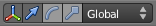 3D manipulators and transform orientation buttons
These buttons are available in object, edit, pose and particle modes.
The 3D manipulators button (CtrlSpace) shows or hides the 3D manipulators at the selected pivot point.
When they are shown we can select the manipulator widgets to show by using LMB ![]() on the the transform, rotate or scale manipulator buttons. We can select (or deselect) more than one widget type by using ⇧ ShiftLMB
on the the transform, rotate or scale manipulator buttons. We can select (or deselect) more than one widget type by using ⇧ ShiftLMB ![]() on them.
on them.
The Transform Orientation button (AltSpace) lets us define how to align the axis set of the 3D manipulators:
- Global shows the manipulators axes aligned with the global axes.
- Local shows the manipulators axes aligned with the local axes of the active object.
- Gimbal shows the manipulators axes aligned with the Euler axes of the active object. If the rotation mode of the object is not set to Euler, the local axes will be used.
- Normal is equivalent to Local in object and particle modes. In edit and pose modes, it's the orientation of the specific element. The Z axis is aligned with the normal in case of mesh vertices and faces. In elements like edges, bones or bezier points it's aligned with its length.
- View aligns the manipulators axes aligned with the current view.
Normal and Gimbal orientations in pose mode.
Paint masking buttons
In vertex, texture and weight paint modes, the Face selection masking ![]() button lets you define faces the vertices of which can be painted with LMB
button lets you define faces the vertices of which can be painted with LMB ![]() . Outside the mask no vertex, texture or weight paint is possible with LMB
. Outside the mask no vertex, texture or weight paint is possible with LMB ![]() strokes.
strokes.
To select faces you can use RMB ![]() on a face, or ⇧ ShiftRMB
on a face, or ⇧ ShiftRMB ![]() for multiple selection. You can also select/deselect all faces with A, border select with B or circle select with C as usual.
for multiple selection. You can also select/deselect all faces with A, border select with B or circle select with C as usual.
In weight paint mode you have an additional button: Vertex selection masking ![]() . This button is used to apply the mask on vertices. The selection tools are the same than the corresponding to face mask.
. This button is used to apply the mask on vertices. The selection tools are the same than the corresponding to face mask.
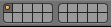 Layer buttons
This set of buttons are available in all modes except edit mode.
The layer buttons define the active (visible) layers. To activate a specific layer, click with LMB ![]() on the corresponding button. To activate multiple layers, use ⇧ ShiftLMB
on the corresponding button. To activate multiple layers, use ⇧ ShiftLMB ![]() .
.
To activate layers with the keyboard, use hotkeys 1 to 9, and 0 (for the 10th layer). These activate the top row of layers; for the bottom one, use hotkeys Alt1 to Alt9, and Alt0 (for the 10th bottom layer). All these hotkeys select a single layer. To activate multiple layers use ⇧ Shift1 or ⇧ ShiftAlt1 to ⇧ Shift9 or ⇧ ShiftAlt9 and ⇧ Shift0 or ⇧ ShiftAlt0.
 Local/scene camera and layers button
This button is available in all modes except edit mode.
When this button is on, the 3D View works with the scene camera and layer configuration.
When the button is turned off, setting a different active camera or layer configuration will only affect that particular view.
 Mesh select mode buttons (Ctrl⇆ Tab)
This button set is only available when editing mesh objects (edit mode). It defines what kind of elements we are able to select and work with: vertices, edges or faces.
When changing the mode, the current selection is translated into the new one, so sometimes this might modify the selection.
 Particle select mode buttons
These buttons are available only in particle mode. It defines what kind of particle elements we are able to select and work with: paths, points or tips.
 Limit selection to visible button
This button is only available when editing mesh objects in edit or particle modes. In texture and solid shading modes, this button lets you select any element of the mesh (button deactivated) or just the visible ones (button activated), that is, the elements that are not covered by other elements in the current view.
 Proportional editing button (O)
This button is available in object, edit and particle modes.
With the button active, interactive actions on objects will also affect other visible objects which are near our selection, depending on the inflience area size (depicted as a circle at the selected pivot point).
Influence area can be changed interactively with Wheel ![]() or PageUp and PageDown. This area can also be changed from the redo panel (Proportional Size) after an interactive transformation, as well as the proportional editing status (Proportional Editing) and fallof (Proportional Editing Falloff).
or PageUp and PageDown. This area can also be changed from the redo panel (Proportional Size) after an interactive transformation, as well as the proportional editing status (Proportional Editing) and fallof (Proportional Editing Falloff).
The fallof selection button (⇧ ShiftO) lets us choose the fallof for the tool, that is, how distance to selection diminishes the proportional effect, always related to the influence area, out of which it has no effect. Each option follows a different mathematical function to calculate the amount of transformation. The icon next to each of them is self explainatory.
In edit and particle modes there is, besides the enabled and disabled state, a third one: connected. In this case, distances are not computed using the "shortest straight distance", but using connected topology.
 Snap buttons (⇧ Shift⇆ Tab)
The snap during transform toggle button activates or deactivates object snapping. The Ctrl key inverts the button effect temporarily while pressed.
There are several snapping modes, which can be selected from the type of element to snap to select button (⇧ ShiftCtrl⇆ Tab):
 Increment: transformations are performed in round increments. In predefined orthographic views the increment size will depend on the actual zoom level. ⇧ Shift hotkey lowers the increment size.
 Vertex snaps the selected objects onto the vertices of mesh objects or heads/tails of armature bones over which the mouse cursor is near.
 Edge snaps the selected objects onto the edges of mesh objects or armature bones over which the mouse cursor is near.
 Face snaps the selected objects onto the faces of mesh objects over which the mouse cursor is near.
 Volume snaps the selected objects inside the volume of the meshes over which the mouser cursor hovers, which defines the XY position of the objects to move (in viewport coordinates). The Z (depth) position will be defined by the center of the volume, calculated from the viewport point of view.
Except for increment snapping mode, you can select which part of the selection will be snapped onto the target using the which part to snap select button:
- Closest will snap the element of the selection which is closest to the target point. That is, the shortest movement possible will be performed. To choose the element, geometries will be considered; for objects without geometry, their center points will be.
- Center will snap the chosen pivot point of our selection.
- Median will snap the median point of the selection. This is equivalent to Center with Median Point selected as pivot point.
- Active will snap the active object center. This is equivalent to Center with Active Element selected as pivot point.
Vertex, edge and face snapping modes provide the Align rotation with the snapping target ![]() button. This button is only available in object mode. When active, it aligns the snapped objects with the normals of the elements onto which they are snapped. In case of edges, the normal depends on the snapping point: the resulting normal is an average of its two vertices, weighted by the distance to each of them.
button. This button is only available in object mode. When active, it aligns the snapped objects with the normals of the elements onto which they are snapped. In case of edges, the normal depends on the snapping point: the resulting normal is an average of its two vertices, weighted by the distance to each of them.
In the case of face snapping mode, we can see the Project individual elements ![]() button. When this button is active, snapping will not depend on mouse cursor position, but on each element position: all objects that overlap with a mesh face will be projected onto it in the viewport Z direction. In this case, you cannot add/remove snapping points.
button. When this button is active, snapping will not depend on mouse cursor position, but on each element position: all objects that overlap with a mesh face will be projected onto it in the viewport Z direction. In this case, you cannot add/remove snapping points.
In the case of volume snapping mode, there is an extra button: Consider objects as a whole ![]() . When this button is active, the full and hollow parts of the mesh are considered as a single block when calculating the middle point to use as depth.
. When this button is active, the full and hollow parts of the mesh are considered as a single block when calculating the middle point to use as depth.
In edit mode, except for increment mode, there is an extra button available: Snap onto itself ![]() . When this option button is active, the elements we are transforming will snap not only on other objects geometry, but in its own geometry too.
. When this option button is active, the elements we are transforming will snap not only on other objects geometry, but in its own geometry too.
Except for increment mode, you can insert snapping points in all modes at the mouse cursor position with A, which will influence the final snapping position. These points are seen on screen as white small circles, except the the last inserted or the last over which the mouse cursor hovered, which is colored orange. AltA removes the orange snapping point.
 OpenGL render buttons
These two buttons are equivalent, respectively, to Info » Render » OpenGL Render Image and Info » Render » OpenGL Render Animation. They are available in all modes.
 Copy/paste pose buttons
 Pause button
This button appears only in rendered shading mode. Use it to pause the viewport rendering. It is available in all modes.