利用者:Thbraun
Material Vector Nodes
Normal Node
The Normal node generates a normal vector and a dot product. Click and Drag on the sphere to set the direction of the normal.
This node can be used to input a new normal vector into the mix. For example, use this node as an input to a Color Mix node. Use an Image input as the other input to the Mixer. The resulting colorized output can be easily varied by moving the light source (click and dragging the sphere).
The (face) normal is the direction of the face in relation to the camera. You can use it to do the following:
- Use this node to create a fixed direction -> output Normal.
- Calcuate the Dot-Product with the Normal-Input. The Dot-Product is a scalar value (a number).
- If two normals are pointing in the same direction the Dot-Product is 1.
- If they are perpendicular the Dot-Product is zero (0).
- If they are antiparallel (facing directly away from each other) the Dot-Product is -1. And you never thought you would use the Vector Calculus class you took in college - shame on you!
So now we can do all sorts of things that depends on the viewing angle (like electron scanning microscope effect or some of techniques described in the section Doc:Tutorials/Textures/Map_Input_Techniques). And the best thing about it is that you can manipulate the direction interactively.
One caveat
The normal is evaluated per face, not per pixel. So you need enough faces, or else you don't get a smooth result
|
Normal Node Example
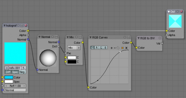
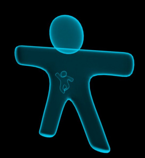
In the shown example the Dot-Product is used to govern the Alpha-Value of the material. The RGB Curves node is used to sharpen the blend between black and white (which results in a range from fully transparent to fully opaque).
The material is an ordinary blue/cyan material with a high Emit value and Z-Transp activated; the background is black. So, as the face angle gets closer to pointing directly at the camera, the material gets more transparent. As the face gets closer to pointing at a right angle to the camera (in this case facing up or down), it gets more opaque.
Using Normal to reflect bumpy-looking textures
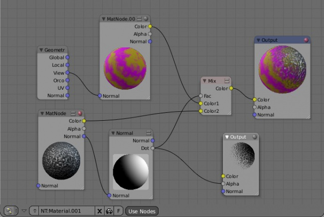
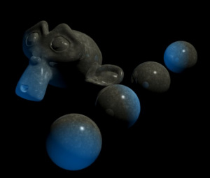
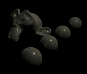
We can use the Normal node to shift the reflection, and thus the shinyness, of a material as shown below. This effect can also be done without nodes, using the materials and texture panels. However, using Nodes allows you to graphically see what is going on to create the final material. The result is that, even though the surface mesh in your model is physically smooth, the reflection makes it look like it has a very fine bumpyness or uneven coating to it, like a really bad paint job or surface prep job was done. This is key to making realistic-looking surfaces.
This map starts out using the geometry node to modify a base material called MatNode.001, shown in the header as MatNode.00 (the "1" was cut off to make the Node skinny, which may happen to you). The Geometry node puts out the View vector set, which flattens the color (removes any shine). MatNode.001 is itself a base tan color with a marble texture that affects and mixes in a purple where the texture is black.
A second material, MatNode, which is the default gray color with a noise texture, is routed through our handy Normal node. The ball has been rolled up and to the right. That puts out a mask that you can see in the Output viewer that is showing the Dot product output. Mixing that mask with the marbleized color and noise material/texture creates the final output for Material.001. As an exercise for the reader, giving the MatNode a color (instead of the grey) would create a specularity effect.
Using the Normal Node to create special Light-Sources
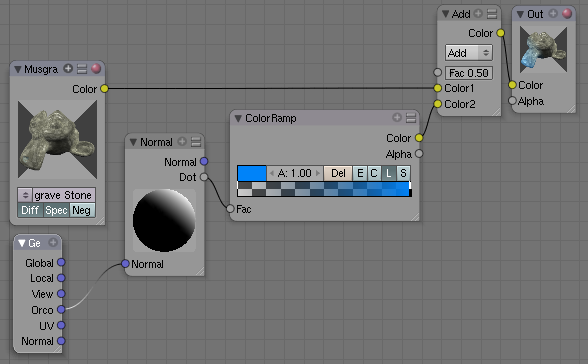
An obvious usage for the Normal node is to use it as a very special lightsource. In (Using the Normal node as a special kind of lightsource) the Orco coordinates are used, so the blue light rotates with the object rotation. If we would have used the Normal coordinates, we would have created a kind of object specific backlight. Global coordinates would give a more ordinary, stationary lamp.
The Fac value in the Mix node (the one with the caption “Add”) determines the amount of added color.
Mapping Node
Essentially mapping node allows the user to modify a mapping. It is possible to use it do same operations as the Map Input panel found in Material buttons allows. It also makes it possible to do several things that are not possible in Map Input. Mapping can be rotated and clamped if desired. Currently mapping node supports only flat mapping type though.
The controls of the node have been ordered in X, Y, Z order. If you want to use the clamping options, try enabling Min and Max.
Mapping Node Example
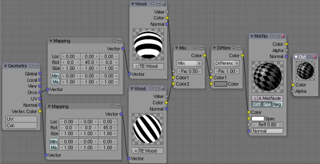
This simple example shows one possible way to use mapping nodes to produce interesting textures. As you can see simply by mapping same texture a bit differently can make it useful. Using the same technique it would be easy to mimic different kind of stripy fabrics.
Vector Curves
Use this node to remap a vector value using curve controls.
