Attic talk:Old/Manual/PartIX/The Non Linear Animation Editor Window (NLA)
Hi Soylentgreen! Right now I study this NLA editor and when I press SHIFT-A I get only option F action. Why only this option? --Igor 17:21, 17 March 2006 (CET)
- Because you've probably defined only one action called "action". --Soylentgreen 18:52, 17 March 2006 (CET)
Thanks! Hmm, what this F action mean then, Frame, Force or Fill action maybe?--Igor 22:46, 17 March 2006 (CET)
- It means it has a "Fake" user, actions are always stored in the file, even if they don't have any real users. So to get rid of them you have to use "Shift-F4". This opens a data browser window. Change to the Action directory, select the action you want to delete, and press "F". --Soylentgreen 07:48, 18 March 2006 (CET)
-- Temporarily moving tutorial here --Matt Ebb 03:48, 27 July 2006 (CEST)
目次
Introducing example
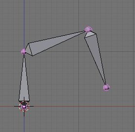
We're going to start with an easy example and build a very simple "Robo-Arm" with three bones (Image 1).
Creating the actions
We're going to define four different actions for the armature.
- Lower the arm from the starting position ("ArmDown")
- Lift the arm back to the starting position ("ArmUp")
- Rotate it by 90 degrees clockwise ("RotCW")
- Rotate it by 90 degrees counterclockwise ("RotCCW")
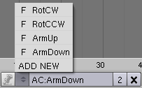
Each of these four action shall last 20 frames. Split the 3D-Window and change to the Action Editor window ![]() . Add four new actions (see Image 2, the 'ADD NEW' item), and name them as shown in Image 2.
. Add four new actions (see Image 2, the 'ADD NEW' item), and name them as shown in Image 2.
These four emtpy actions are going to be "filled".
In order to make movements seem fluid and smooth, one action must begin with the same pose that the previous action ends with. The following shows how to make poses for the "ArmDown" and "ArmUp" actions; it also shows how to make the actions seamless by duplicating poses.
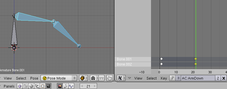
We begin with the action "ArmDown". Select the "ArmDown" action in the Action Editor and change the armature to Pose Mode. Select the second and third (two outer) bones, press I and choose Rot in the appearing InsertKey menue. Advance 20 frames forward to frame 21 (press the ↑ twice) and put the armature in the desired end position. Again choose the two outer bones and insert the second IPO key (I->Rot) (Image 3).
Now change to the action "ArmUp" and go to frame 1 (press the ↓ twice). The arm should remain in "ArmDown's" end position. Save the IPO-Keys for the two outer bones (I->Rot). This will make the first transition - from "ArmUp" to "ArmDown" - seamless.
Switch back to the "ArmDown" action. The arm changes to "ArmDown's" starting position. Copy the pose (Menu >> Pose >> Copy Current Pose) ![]() . Change to the "ArmUp" action, go to frame 21. Insert the pose (Menu >> Pose >> Paste Pose), then save the IPO keys. This will make the second transition - from "ArmDown" to "ArmUp" - seamless.
. Change to the "ArmUp" action, go to frame 21. Insert the pose (Menu >> Pose >> Paste Pose), then save the IPO keys. This will make the second transition - from "ArmDown" to "ArmUp" - seamless.
The rotation of the arm around itself will be created nearly exactly the same way. However, use the first bone for the rotation, so that the rotation movement is independent of the up/down movement. First create the rotation of 90 degrees clockwise, then the rotation back to starting position.
Now we've defined the four actions and are going to combine them in the NLA Editor.
NLA
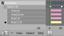
Change from the Action Editor to the NLA Editor window ![]() . The name of the object with an action appears on the left hand side of the window (see Image 4).
. The name of the object with an action appears on the left hand side of the window (see Image 4).
Now we have to add so called "strips". These "strips" are actions, which can be combined in the NLA editor.
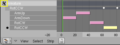
Move the mouse over the name of the object and press ⇧ ShiftA. (If you get the error message Object has not an Action the mouse was probably over an empty part of the window). Select Add Action from the popup window . Repeat this for the rest of the four actions.
Only one action is active (indicated by a black dot), only the IPO symbols (the white diamonds above the strips) of the active action are shown (see Image 5). You can select and move the actions. Move the actions to a position as shown in Image 6. Keep the Ctrl key pressed while moving, to lock the strips to the frames. Use ⇧ ShiftS (Snap to Frame) to synchronise a strip with the frames afterwards.
Start the animation (⇧ ShiftAltA). You will notice that only the active action is executed. Click on the top-left button in the NLA area (see the yellow bordered button in Image 6. It doesn't seem like a button but it is one). The button now shows the NLA icon. Now you are in NLA mode.
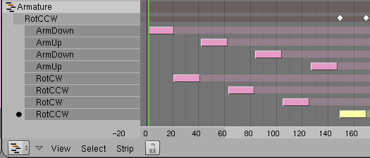
The strips are evaluated top to bottom. That is, channels specified in strips later in the list override channels specified in earlier strips (as long as the same IPO's are affected). The strips in Image 6 don't overlap, so the four actions are exectued one after the other. You can move strips to get composite movements. You can copy strips to get repeated actions. You can scale strips, blend them in and out and "add" movements. You can "hold" the end position of the objects at the end of the strip.
The strip properties are changed via the Transform Properties panel, which you call with N. Activate the Hold button for every strip, so that the position at the end of the action is kept. See the reference section for the other options.
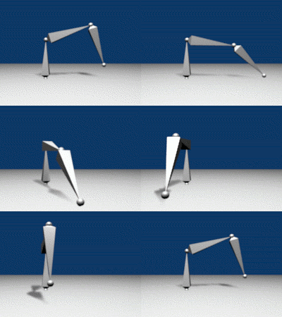
In Image 7 you see a composite - albeit simple - action. Observe the NLA icon in front of the object's name. Of course, you could achieve the result in Image 8 in other ways, but it is more intuitive and offers great flexibility to work with layered, cummulative movements.
Note: Because you can't render bones in version 2.41, objects were parented to the bones to render the animation for Image 8.
Stride Support
The Stride Support solves an otherwise complicated synchronisation problem. If a body is moved a certain distance by an Action, at what time is the next Action to take place, so that action and movement are always in sync?
Two simple examples:
- A wheel rolling on a plane covers a certain distance with each revolution.
- With each step you cover a certain distance.
It is easy to synchronise a single movement, but what if the object has to become faster or slower along it's path? There is a second problem with a stride, because each foot stays a certain time at the floor.
- To solve the first problem, we will use a Stride Path
- To solve the the second problem, we have to use an additional Stride Bone.
Therefore we will begin with the wheel problem, because it is simpler to solve. The more simple way without a Stride Bone may also be used, when the contact with the ground is very short - or if one can't see it.
Example 1: Stride Path
Start with a new scene, remove the cube. Change to sideview (1 NumPad). Add an armature, one bone is enough. Change to Pose Mode and select the bone.
Split the 3D-window, change to the Action Editor. Add a new action, call it "RotCW". Add five Ipo's, each ten frames apart. The first IPO is the starting position (I->Rot). Go forward ten frames, then rotate the bone by 90 degrees clockwise; repeat for the rest of the five Ipo's. This action is very simple but can show everything important.
Change to topview in the 3d-window (7 NumPad). Add a path with Space>>Add>>Curve>>Path. (We could use a "Bezier" or a "Nurbs" curve as well, but then we would have to add a Speed IPO curve later. Since the Path already has a Speed curve, it is used for this example.)
Make sure the path is in object mode (⇆ Tab). Select the armature (RMB ![]() ). Make sure the armature is in object mode. With the armature still selected, select the path with ⇧ ShiftRMB
). Make sure the armature is in object mode. With the armature still selected, select the path with ⇧ ShiftRMB ![]() . Both the armature and the path should now be selected (it is important that the armature is selected first).
. Both the armature and the path should now be selected (it is important that the armature is selected first).
Click CtrlP and select Follow Path from the popup. This makes the path the parent of the armature (a modifier doesn't work here). If you press AltA in the 3D window, the bone rotates one time around itself and is moved along the path in 100 frames.
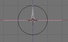
To symbolise the "Wheel" add a Circle with 8 vertices in side view, use a SubSurf modifier level 2, and scale the circle on a diameter of exactly two blender units. Change the armature to pose mode and parent the circle to the bone (Image 12). Now armature and circle move synchroniously.
A note about parenting
It is important to switch the armature to pose mode before parenting. The child (the circle) inherits the movement of its actual parent. Since the bone as an object is parented to and follows the path, if you parent the circle to the bone as an object, it will only move along the path and not rotate. The rotation action is found only in the bone as a pose. So to have the circle rotate, you must parent the circle to the bone as a pose. Also, remember to select child object first, and the parent object second. |
Now (finally) to the Stride Path. The circle shall move exactly one perimeter along the path for every complete rotation. Seen from the "Stride path" point of view: repeat the action after the armature has moved the distance Stride along the path. The distance Stride has obviously to be the circle perimeter - after a complete rotation the circle is in it's starting position and the action has to be repeated.
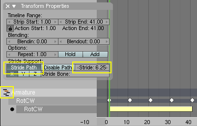
If you have a circle with a known diameter it is easy to get the perimeter, it's simply (diameter * Pi), in this case (2 blender units * 3.142 = 6.284 blender units). We have to use this value for Stride. Change to the NLA editor, add the "RotCW" action for the armature. Switch to NLA mode. Select the just added "RotCW" action if it's not already selected, press N, the Transform Properties panel appears. Switch Stride Path to on and set the Stride value to "6.284" (Image 13).
Rotation and movement along the curve are now synchronised. Each 6.248 blender units movement along the path the circle has rotated one time around itself.
To direct where the wheel should go, select the path. Switch to edit mode (⇆ Tab). Move the curve points to the desired shape. When working with the path in edit mode, the changes to the path do not affect the objects parented to the path as an object - rather, the objects simly follow the new path shape in the same manner as they followed the old path shape.
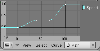
The "wheel" begins slowly and stops slowly. To change the velocity along the path, select the path. Change to the IPO Curve Editor. Select IPO Type "Path". The Speed curve is (fortunately) not the velocity but the relative position along the path. Edit the Speed curve (CtrlLMB ![]() adds new points). The position along the path changes accordingly. The object stands still on horizontal sections, it moves fast on steep sections (Image 14). Rotation and movement along the path stay synchronised.
adds new points). The position along the path changes accordingly. The object stands still on horizontal sections, it moves fast on steep sections (Image 14). Rotation and movement along the path stay synchronised.
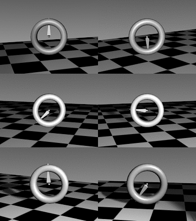
The result: the "Wheel" follows the curve, all global movements of the "Wheel" can be changed with the curve (Image 15).
Useful tips
|
Example 2: Stride Bone
As you've seen in our first example, the armature object moves steadily along the path. If you want a bone to hold it's movement you have to define an opposite movement, that cancels out the movement of the armature object. To define this movement we'll use a Stride Bone. The total movement of the Stride Bone (in Blender units) from the first to its last Ipo defines the Stride Parameter, the total movement along the path for one action.
We're going to use a very simple example, which could be improved a lot for actual usage. But again - it shows everything that is necessary. A "foot" with "lower leg" shall hop first in place, and than begin to move forward.
"Foot" Bone Rigging
- Open a new scene, remove the cube and change to sideview (1 NumPad).
- Add an armature, rotate the bone by 180°.
- Extrude the second bone 0.5 BU (Blender units) 90° to the right ("Foot").
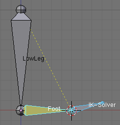
- Select the tip of the "Foot" bone and snap the cursor to the selection (⇧ ShiftS->Cursor to Selection). Add a third bone (don't extrude) (Space->Add->Bone), this will become the IK-Solver. Rotate and scale this third bone as you see fit (Image 17).
- Rename the bones, the first bone gets the name "LowLeg", the second one "Foot", the third one "IK-Solver".
- Select the "IK-Solver" bone. Switch to Pose Mode. Select the "Foot" bone with ⇧ ShiftRMB
 . Click CtrlI-> Add IK-Constraint->To Active Bone.
Our "Rig" is ready, now to create poses:
- With the rig selected, make sure you are in Pose Mode.
- Split the 3D-Window, change to the Action Editor. Add a new action, call it "Hop".
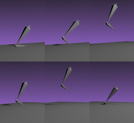
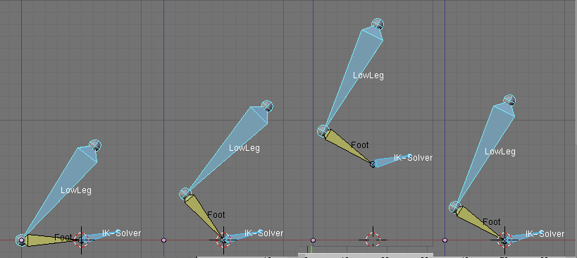
- Create poses for the "LowLeg" and the "IK-Solver" bone. The "Foot" will be moved automatically. Create four unique poses (Image 18) using I->LocRot.
- For this example, use only vertical movement in the "IK-Solver" bone, and avoid horizontal movement.
- Insert the first pose again at the end (Image 20) (not shown in the image) for a total of five poses.
"Stride" Bone Rigging
After all these preparations the Stride Bone will be added.
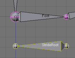
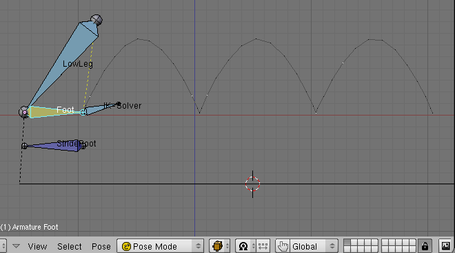
- Add a fourth bone in Edit mode, rename this bone to "Stride Root". The "Stride Root" bone has to point in the opposite direction of the armature movement. The exact absolut positioning along the X-Axis doesn't matter, but the relative movement has to be exact (Image 19).
- Change to Pose Mode and add poses for the stride bone to the action "Hop" (see note below).
How the Stride Bone works
|
- We're going to synchronize the "Stride Root" bone with the tip of the "Foot" bone in the frames 1-11 and 51-61. Define following Location poses (I->Loc) for the stride bone:
- Frame 1: Start position
- Frame 11: Start position again
- Frame 51: The "Leg" object shall move between Frame 11 and Frame 51. Therefore we have to move the Stride Bone the equal distance in the direction of the movement. Move the Stride Bone one BU in the direction of the movement and add the next Ipo.
- Frame 61: Since the (tip of the) leg rests on the floor between frame 51 to 61, the Stride Bone has to stay in it's position. Add the last Ipo.
Insert the path:
- Change to Object Mode and to topview (7 NumPad).
- Space->Add->Curve->Path.
- Change to Object Mode, select the Armature in Object Mode and select the path with ⇧ ShiftRMB
 .
. - Parent the Armature to the Curve (CtrlP->Follow Path). If you press AltA in the 3D-Window, the Armature follows the path.
The setup for the stride bone happens in the NLA Editor:
- ⇧ ShiftA->Add Action->Hop
- Change to NLA-Mode (LMB
 on the icon with the little man next to the armature name).
 - N to open the Transform Properties Panel.
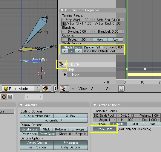
- Activate Stride Path, "Y" as axis for the Stride Bone.
- Activate the correct movement by:
- typing "StrideRoot" in the Stride Bone field in the Transform Properties Panel.
- or, while "StrideRoot" bone is selected in pose mode, click the Stride Root button (found in the Armature Bones panel (see image 21)).
Press AltA in the 3D-Window or ⇧ ShiftAltA in the NLA Editor. The armature moves hopping along the path. By modifying the Speed-Ipo of the curve and the Ipos of the "Stride Bone" you can change the speed, direction and character of the movement, without changing the Ipos of the "Hop" action.
Change the movement by manipulating the Stride Bone
Select a bone in Pose Mode, press W and choose Calculate Paths to draw the path of the bone in the 3D-Window (Image 22).
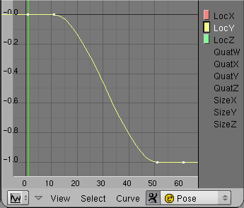
The Speed-Ipo of the curve rules the velocity of the movement along the path. With a Stride Bone you can manipulate the distance of the stride and the general character of the movement. Select the Stride Bone in Pose Mode and change to the Ipo Curve Editor (Image 23). If you set LocY to 2, the jump is twice as far and needs twice the time, if you set LocY to 0.5 accordingly faster and shorter. See Blender Stride Tutorial for complete examples.
Summary
- Create an action in place for the armature.
- A Stride Path is a curve with a Speed-IPO, normally a Curve->Path object.
- The armatue object is parented to the curve in object mode, so that it will follow the curve. A Follow Path constraint does not work as a stride path.
- An object will be skinned as usual. After a certain distance in blenderunits the action shall be repeated. You have to measure (or calculate) that distance. Use this value for the parameter stride.
- The action is added in the NLA Editor window, the NLA Editor has to be in NLA mode.
- Turn on Stride Path for the action in the Transform Properties panel and fill in the Stride parameter.
- A Stride Bone allows for finer synchronisation of single bones with the objectmovement of the armature in total. You can "clamp" bones to their position, while the armatureobject moves along the path.
- The Stride Bone has not to be parented or otherwise fixed to the other bones, he only has to be part of the action.
