Doc:Theory/Modeling/Boolean Operations
editors: this page was copied from a PDF: http://blender.instinctive.de/siacg06-printed.pdf.gz, it's not done yet, the text misses some code parts, all images and tables
Ibero-American Symposium on Computer Graphics - SIACG (2006) P. Brunet, N. Correia, and G. Baranoski (Editors)
Boolean Operations in Open-Source Blender Project Marc Freixas, Sergi Grau and David Silva Grup d’Informàtica a l’Enginyeria (GIE), UPC, Barcelona, Spain
目次
Abstract
This paper describes the work of a new implementation of the Boolean operations of Blender. Blender is a modelling and animation 3D software with GNU General Public License (GPL). Boolean operations are a useful tool for modelling. Previous implementations of Blender Boolean operations have some drawbacks and the Blender users are not totally satisfied with them. The proposed implementation avoids the existing drawbacks of previous implementations and helps users in their modelling stage.
Categories and Subject Descriptors (according to ACM CCS): I.3.4 [Computer Graphics]: Graphics Utilities I.3.5 [Computer Graphics]: Computational Geometry and Object Modelling I.3.6 [Computer Graphics]: Methodology and Techniques
Introduction
In this paper we present the work consisting of a new implementation of Blender Boolean operations. Blender is a modelling and animation 3D software with GNU General Public License (GPL) and it is maintained by a really active community. Blender features are closed to other commercial programs but some aspects still need to be improved.
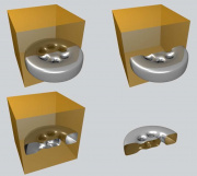
Many important editing operations can be expressed in terms of Boolean operations on closed objects. Shapes are created using union, intersection or difference. For example, a union operation merges shapes; the difference operation scoops out a hole (see Figure 1). However some users do not use Boolean operations because the original implementation in Blender provides unsatisfactory results. It generates meshes that have duplicated vertices, and they are not sewed (see Figure 6 b). Some developers have offered alternative solutions to this problem. For example, there is one script called MegaBool, that implements Boolean operations in Python. The results of MegaBool are usually satisfactory, but it is a fact that interpreted languages do not have an acceptable computational cost, and it is not easy to integrate this script inside the Blender’s source. Another problem of MegaBool is that it does not take into account the properties of the original objects in the final object (see Figure 7 c). The properties of an object do not matter in the modelling stage, but they are needed in the rendering stage.
Previous work
Boolean operations can be performed in several solid modelling system. Constructive Solid Geometry (CSG) is commonly used for specifying solid models as Boolean combinations of primitives [Req80, HHK89]. CSG expressions can be converted to a polygonal mesh through boundary evaluation, but conversion algorithms are too slow for real-time graphics [RV85, Taw91, KCF ∗ 02, BGM93]. Requicha and Voelcker [RV85] introduce first the boundary evaluation and merging process. Their approach consists basically of three stages. First, it splits the objects by the intersection region (subdivision stage). Second, it classifies faces with regard to the objects (classification stage). At last, it reconstructs the resulting object using those faces that were correctly classified according to the type of Boolean operation (See union, intersection or difference in Table 1) (reconstruction stage).
<image here well a table> Table 1: Object classification according to the type of Boolean operation.
There are several authors that propose different techniques for the subdivision stage. Requicha and Voelcker [RV85] and Miller [Mil88] use an edge-by-edge approach. Mäntylä [Män86] suggests an algorithm called vertex neighbourhood classifier based on a edge-by-face strategy. Later, other authors like Hoffmannm, Hopcroft and Karasick [HHK89] and Chiyoruka [Chi88] also suggest boundary evaluation algorithms based on a face-by-face approach. Kunwoo Lee [Lee99] describes an algorithm that computes the intersected segments between two faces (called xegment). Then it takes into account the xegments to subdivide each face. Rivero and Feito [RF04] present a technique to detect intersection between triangular faces, and their consistent subdivision.
Binary Space Partitioning Trees (BSP trees [FAG83]) have been used for classification in several strategies ( [TN87, NAT90, PY89]). The BSP tree of a solid object can be used to classify any point with regard to the object. The point can be inside (IN), outside (OUT) or on the boundary (ON) of the solid. Using this basic test, the classification of one face according to a solid object is also simple. In the classification stage, there is one BSP tree for each object, and the faces are classiied using the BSP of the other object.
Boolean operations algorithm
The implementation presented in this paper had to fit inside an existing platform (Blender), where the data structure used to represent an object is a mesh of triangles or quads. This fact simplifies the representation of the general B-Rep structure.
For easiness and robustness, Boolean union (∪) and difference (−) are implemented in terms of intersection (∩) and
<image here> Figure 2: Boolean Operation Algorithm’s Pipeline can be subdivided into dependent or independent on the type of the operation (left). This pipeline can also be subdivided into preprocess, core or postprocess stages (right).
complement (¬) (See Table 2). Complement operation consists in flipping normal vectors and inverting vertex order of all the mesh faces.
<image here> Table 2: ∪ and − expressed in terms of ∩ and ¬.
This simpliication subdivides the pipeline of the Boolean operations algorithm in two kind of stages: dependent or independent on the type of the operation (∩,∪,−) (See Figure2).
The core of the strategy follows the three stages explained before: subdivision, classiication and reconstruction stages. Before these stages, there is a preprocess that prepares all the structures needed for the next stages. Firstly, the input meshes are negated if it is required. The other tasks of the preprocess are explained on each stage that it needs. After all the stages, there is a postprocess that negates the output mesh in case it is needed (in ∪ operation).
Subdivision stage
The subdivision stage is based on Kunwoo Lee [Lee99], but it is simplified because the input faces are only triangles (quads are split in the preprocess). In this face-by-face approach we intersect each face of one object against the faces of the other object. For each couple of faces, it computes their xegment and splits both faces.

Xegment creation process
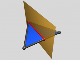
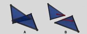
This process computes the possible intersection between two faces, intersecting each face against the plane of the other face. Intersection between the face and the plane generates a segment with one or two points that can lie on vertices or edges of the face (see red segments in Figure 3). When
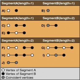
there is intersection between both faces, the segments are overlapped. Figure 4 shows all the conigurations of two segments. Two faces do not intersect when there are not two segments or when they have coniguration A or B. The region shared by both segments represents the intersection segment between both faces (xegment).
When the xegment does not begin or end on a face vertex, a new vertex is created and added to the mesh vertices set. When it begins or ends on a vertex of only one face, this one is used. But when the xegment begins or ends on vertices of both faces, one of them replaces the other. The vertex that persists is used in the split process. This criterion of vertex replacement avoids a posterior sewing process of the final mesh in the reconstruction stage.
Split process
This process subdivides the faces taking into account the xegment computed in the previous process (see Figure 5). Figure 6 shows the possible locations of a xegment (red) with regard to a face and the new edges (green) resulting from the splits. The old faces are discarded and the new generated faces are added to the face-by-face process.
Classification stage
This stage receives a set of faces for each object (that are original faces or come from original faces). For both objects, this stage classiies its faces using the BSP tree of the other object. The BSP trees had been computed in the preprocess (see Figure 2).
The faces resulting from the subdivision stage can only have vertices classiied as IN and ON, or OUT and ON. This happens due to the BSP tree being constructed using the object faces and these same faces subdivide the face of the other object, if it is required. This property allows to simplify the classiication as IN, OUT or ON and accelerates this stage. In case that at least, one of the vertices is IN, the face is also IN. If one of the vertices is OUT, the face is OUT. Otherwise the face is ON. When a face is classiied ON we compare its normal vector with the plane normal vector of
<image here> Figure 6: All configuration of the xegment inside a triangle. Red segments in B are the resulting xegment on each triangle, and green segments are the new edges created by the splitting process. Triangles A and B do not need to split. Configurations {C,D,E} and {F,G} use the same split strategy. Cases H, I, J and K do a particular split
<image here > Figure 7: Left object represents the result of a Boolean operation without reconstruction stage. Right object represents the result of a Boolean operation with reconstruction stage.
Reconstruction stage
The reconstruction stage has been simpliied because there are not duplicated vertices but only those faces that represent the boundary of the final object, and all the faces are connected. These faces could be a result of the Boolean operation. The drawback of this output is that it could be very fragmented (see Figure 7). The objective of this implementation is to help Blender users to design their objects. So if they receive a mesh with unnecessary split faces, they could be disappointed with the result. For this reason, we use the reconstruction stage to reduce the number of faces, merging those faces that come from the same original face. This stage generates a mesh of triangles and quads, although it receives only triangles. Only convex quads are allowed so before creating a quad we check its convexity and we discard it if it is not a convex quad.
The reconstruction process is subdivided in two stages:
- Merge of faces removing vertices.
- Merge of faces removing edges.
Both are executed successively, until one of them ends without producing any merge.
Merge via removing vertices
We say that a vertex is candidate to be removed or removable if it didn’t exist on the initial vertices set. For this reason, we only can remove those vertices generated during one of the intermediate Boolean operation stages. The rest of vertices and faces without removable vertices will be ignored during this stage.
For each removable vertex vi of a mesh M, the first step consists in finding the set of faces Li1 ...LiN where • Li j is the faces set of M that contains vi and come from the original face C j. <image here> Figure 8: Possible configurations of merge faces.
<image here> Figure 9: The vertices v prev and vnext of v inside a triangle are computed according to the vertex order.
• L = Li1 ∪ ... ∪ LiN is the faces set of M that contains vi . The next step consists in the application of merge patternson those faces in the same set Li j (see Figure 8 A-D). Eachof these patterns receives two faces with vi , and in case ofsuccess it produces a new face without it as a result of themerge. The new faces are added in a new set L while themerged faces are removed from their corresponding set Li j .The process ends when neither of the patterns can’t be applied or all set Li j is void. In the first case, we have two ormore faces that could not be merged, so vi can’t be removed
<image here> Figure 10: The vertices v prev , vnext and vo p p of v inside a quad are computed according to the vertex order.
and the mesh keeps intact. In the second case, vi and the faces of L are removed from the mesh, and the faces of L are added.
The patterns B-D in Figure 8 present as a special feature, the fact that they require to remove a second vertex in order to merge the input faces. This second vertex is added to a list of pending vertices that must be removed to eliminate vi , generating a chain of remove-dependencies between the vertices. If the process fails for one of them, neither can be removed. Otherwise, the vertices and their faces are removed, and the new merged faces are added.
Figures 9 and 10 show deinitions of v prev , vnext and vo p p and here we deine some functions used later:
Here is a long string of code that will not display, will need an image here.
Merge via removing edges
This stage is much simpler than the previous one. It generates quads merging two triangles, using the pattern of the Figure 8 E, when these tringles share an edge and come from the same parent face. If this pattern is successful, the input triangles are removed from the mesh and the resulting quad is added to its faces set. This pattern can be formalised as follow:
another piece of code
Results
Table 7 shows some figures that compare the original Blender Booleans with our implementation and the Mega- Bool script. We can see that the original strategy produces too many triangles and the meshes are not solids (a,g,j). The other two strategies preserve original quads (b,c).MegaBool constructs clean meshes with spectacular nice triangles (l), but sometimes generates unexpected holes (i) and does not assign the correct property values for each faces, like its material (c). In the second row (d,e,f), two solids that are coincident by one face and one vertex are joined. Megabool (f) computes a wrong union operation, and the original strategy (d) does not detect the coincidence. The performance tests have been done in a Pentium IV 3Ghz with 512Mb of memory. We can consult the used samples sizes in the Table 3. In Table 4 we can observe the results of computing the different Boolean operations with the sample models. In this Table we can see that the old version is faster than the new one, but we have seen this one does not compute the solid object well. In the case of the Megabool Python script, it is considerably slower. For the dense models it has memory problems and it does not compute the result. This low performance is due to the interpreted language implementation. In Table 5 we show the performance of each pipeline stage. Themost expensive stage in the Boolean process is the subdivision stage, followed by the reconstruction stage. As a future work we aim to improve the subdivision stage so that it realizes less and better divisions, and as a consequence we will be able to reduce the work for the reconstruction stage.
Conclusions and future work
The present work has allowed to introduce us to the world of free software and to be able to collaborate with the Blender community. The fact that everybody has access to the Blender source code turns it an ideal platform for the development of projects related to computational geometry.
We recoded Blender’s Boolean Operations, and they return intuitive results that conserve properties of the input objects. This new implementation is available since Blender 2.40. We will try to speed up the algorithm by simplifying the subdivision stage. This stage will be divided in two substages. First we will compute all xegments, using a face-byface test, without splitting the triangles. Next we will tesselate all faces avoiding unnecessary splits.
Acknowledgements
This work has been made thanks to the program of scholarships "Summer of Code 2005" of Google for the development of free software projects. We thank Alex Ewering and the Blender community for their aid and technical support. This work has been partially supported by a CICYT grant MAT2005-07244-C03-03 and TIN2004-06326-C03-01.
References
- [BGM93] BANERJEE R. P. K., GOEL V., MUKHERJEE A.: Efficient parallel evaluation of csg tree using fixed number of processors. In SMA ’93: Proceedings on the second ACM symposium on Solid modeling and applications (New York, NY, USA, 1993), ACM Press, pp. 137–146.
- [Chi88] CHIYOKURA H.: Solid Modeling with Designbase: Theory and Implementation. Addison-Wesley Longman Publishing Co., Inc., Boston, MA, USA, 1988.
- [FAG83] FUCHS H., ABRAM G. D., GRANT E. D.: Near real-time shaded display of rigid objects. In SIGGRAPH ’83: Proceedings of the 10th annual conference on Computer graphics and interactive techniques (New York, NY, USA, 1983), ACM Press, pp. 65–72.
- [HHK89] HOFFMANN C. M., HOPCROFT J. E., KARASICK M. E.: Robust set operations on polyhedral solids. IEEE Comput. Graph. Appl. 9, 6 (1989), 50–59.
- [KCF�02] KEYSER J., CULVER T., FOSKEY M., KRISHNAN S., MANOCHA D.: Esolid–a system for exact boundary evaluation. In SMA ’02: Proceedings of the seventh ACM symposium on Solid modeling and applications (New York, NY, USA, 2002), ACM Press, pp. 23–34.
- [Lee99] LEE K.: Principles of CAD/CAM/CAE Systems. Addison-Wesley Longman Publishing Co., Inc., Boston, MA, USA, 1999.
- [Män86] MÄNTYLÄ M.: Boolean operations of 2-manifolds through vertex neighborhood classification. ACM Trans. Graph. 5, 1 (1986), 1–29.
- [Mil88] MILLER J. R.: Analysis of quadric-surface-based solid models. IEEE Comput. Graph. Appl. 8, 1 (1988), 28–42.
- [NAT90] NAYLOR B., AMANATIDES J., THIBAULT W.: Merging bsp trees yields polyhedral set operations. In SIGGRAPH ’90: Proceedings of the 17th annual conference on Computer graphics and interactive techniques (New York, NY, USA, 1990), ACM Press, pp. 115–124.
- [PY89] PATERSON M. S., YAO F. F.: Binary partitions with applications to hidden surface removal and solid modelling. In SCG ’89: Proceedings of the fifth annual symposium on Computational geometry (New York, NY, USA, 1989), ACM Press, pp. 23–32.
- [Req80] REQUICHA A. A. G.: Representations for rigid solids: Theory, methods, and systems. ACM Comput. Surv. 12, 4 (December 1980), 437–464.
- [RF04] RIVERO M. L., FEITO F.: Refinamiento de mallas triangulares. Aplicación para el cálculo de operaciones Booleanas en 3D. XIV Congreso Español de Informática Gráfica (2004), 77–90.
- [RV85] REQUICHA A., VOELCKER H.: Boolean operations in solid modeling: Boundary evaluation and merging algorithms. P-IEEE 73 (1985), 30–44.
- [Taw91] TAWFIK M. S.: An efficient algorithm for csg to b-rep conversion. In SMA ’91: Proceedings of the first ACM symposium on Solid modeling foundations and CAD/CAM applications (New York, NY, USA, 1991), ACM Press, pp. 99–108.
- [TN87] THIBAULT W. C., NAYLOR B. F.: Set operations on polyhedra using binary space partitioning trees. In SIGGRAPH ’87: Proceedings of the 14th annual conference on Computer graphics and interactive techniques (New York, NY, USA, 1987), ACM Press, pp. 153–162.
Table 5: Execution times for each Boolean stage.
Table 6: Union of two cubes. (a&b) Some vertices lay on edges. The result is not a solid mesh and it has a lot of unnecessary vertices. (c) The result is a well sewed mesh with the minimum number of necessary vertices.
Table 7: Comparison between the different strategies.


