Community:Science/Robotics/SimulatorInterface
目次
A Robotics Simulator User Interface for Blender
This script contains the template for an interface allowing a user to perform all the relevant actions in setting up a robotics simulation. The main goal of this script is showing what the User Interface of a robotics simulator might look like. As of yet none of the actions performed on the script have any relevant effect on the Blender scene, though the code can easily be extendend with this.
The script is far from functionally complete, but most remaining code can easily be derived from the existing code.
The script can be downloaded here.
This is the Class Diagram of the underlying data structure: (link)
This is the (envisioned) menu structure of the interface: (link)
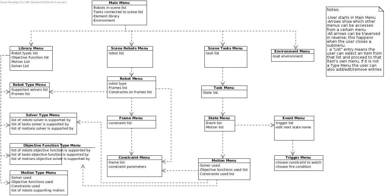
Notes on the code
Intro
There are two main sides to the simulation interface code: The datastructures module and the interface script.
Datastructures
The Datastructures module contains the domain logic. Each concept relevant in a simulation is captured as a class. These classes can interact with each other, but for the moment only in terms of data storage. In the current revision the setting up of the simulation variables is the goal. The actual acting out of the simulation is not yet modelled. Some extra associations or classes might be needed to support runtime requirements, such as updating Frame positions each step.
Here is a glossary of the classes in the module. Not all described functionality is supported by the diagram, which only models the storage of the elements, not their actions.
- A Scene is the "world" a simulation is acted out in
- A Frame is a frame of reference with XYZ axes. Each Frame has a Parent (None for the root frame) and can have children. Each Frame knows the location of the origins of its child Frames in its own coordinate system. Frames know their children or parents via a FrameLink.
- A FrameLink describes the relation of a child Frame to its parent in terms of rotation and translation.
- A Robot represents an agent in the simulation. It has a rootFrame, which provides access to the hierarchy of Frames the Robot consists of. A Robot also has a list of supported Solvers and ObjectiveFunctions.
- A Task is defined as a Finite State Machine. The states are simply called "State", while the connections between the states are modelled as "Events". Each State has one or more Events, each leading to another State. Each Event has one or more "Triggers" that each wait for a Constraint (more on that later) to fulfil a specific condition (e.g. a distance nearing zero).
- A State can contain of one or more "Motions", representing a number of constraints (on one or more robots) working together. These each have one or more Constraints, as well as a Solver (algorithm) they use for fulfilling these Constraints, and a mapping of ObjectiveFunctions on the Robots involved in the Motion. ObjectiveFunctions represent a sort of over-arching constraint on a whole robot (e.g. "minimize expended energy").
- An Event is the connection between two states, like the arrows in a FSM. It has multiple Triggers. When one of these triggers fires, the event happens and the Task moves to a new State.
- A Trigger watches a Constraint. If the Frames involved in the constraint satisfy a certain condition, the Trigger fires. Any Events watching this Trigger are notified of the firing.
- Constraints are the different subparts of a Motion. Each Constraint is defined for two or more Frames (these are local coordinate systems allowing relative movement, one Frame for each joint the robot has).
- A Solver is an algorithm that solves the imposed Constraints on a Motion with respect to the concerned ObjectiveFuncions.
- An ObectiveFunction is a function active on a whole robot, influencing all its Frames' Constraints.
Interface
The separate script has two functions:
- Providing interface elements in a Blender panel for interaction with the simulation parameters - Linking the domain with the Blender scene.
The first function is fulfilled by the methods of the OBJECT_PT_robosim panel class. Each of these methods contain the interface code for one menu. This interface code consists of mainly these things:
- Text via the layout.label() function
- Checkboxes via layout.prop(bpy.context.scene, "X", text="Y"), where X is the name of a EnumProperty connected to the scene and Y the name to be displayed for the box.
- Text-input boxes via layout.prop(bpy.context.scene, "X", text="Y"), where X is a StringProperty connected to the scene and "Y" is the name to be displayed for the box.
- Lists of elements with add/view/remove buttons to operate on the selected element. These work by calling the drawList-method. More on that later.
The operators referenced in the menu code are called each time the corresponding button is pressed.
All the "*Menu"-operators inherit from the MenuToggle class. This means that they have a boolean attribute "active". Each time the operator is called this attribute is toggled. This allows us to use the same operator for closing and opening a menu.
Each draw-method is responsible for drawing either itself or an underlying menu (e.g. drawTaskMenu for drawing states). If a draw-functions detects an underlying menu is active, it calls that menu's draw function instead of drawing itself. This way, the top draw call passes through all draw-methods down to the lowest open menu.
Occasionally an operator with menuToggle as parent will do some extra operations in its own invoke method. Since the draw-methods are called everytime the screen is refreshed, this provides an easy way of preparing some global variables, like lists, that have to be used in a newly opened menu, while running the code only once.
Roadmap for further development
This script is far from finished. In this section an outline of the remaining work is presented.
Short Term
- Each element in the menu diagram must have its own menu
- The library menu and submenus need to be finished
- "X Type" Menus must be linked to the scene instance menus (Robot to Robot Type, for instance)
- The Constraint Menu must be able to handle being called from the Frame Menu context, as well as form the Motion Menu Context
- FSM's consisting of States and Events have to be created through a combination of their respecive menus. Which states are accessible from which events and vice versa is yet to be decided
- View all constraints on robot option must be included
- Environment menu must be created
- The code needs to be refactored: lots of duplicate code in the draw-methods can be delagated to new methods
Long Term
- Integration with the earlier work of Peter Roelants
- Extending Blender with the necessary functionality