Dev:Source/Architecture/Overview
目次
[非表示]Blender Architecture Overview
by Ton Roosendaal
- THIS DOCUMENT IS FROM 2003! HALF OF THIS IS OBSOLETE NOW!
Over the past 8 years Blender's codebase has been changing and expanding a lot. During the corporate (NaN, 2000-'02) years, also several attempts were made to restructure the code, to allow more people to work with it, and to bring functional parts of code together in logical chunks. However, as with most corporate development, marketing demanded deadlines and releases, creating a conflict between 'what's possible' and 'what's required'. Much of this restructuring work was only partially finished when the company shut down in 2002. The sources that were released in october 2002 were actually a 'snapshot' of an intermediate state of development, explaining quite some of the confusion people have with the code.
In this document I will focus on revealing what the original design concepts where, how that was implemented, and how this currently can be found in the source tree. This information is relevant for all current development, since following original design principles can ease up coding work a lot.
A secondary target of this document is to provide hooks we can use for a further 'modularization' of Blender.
Whether or not Blender was good or bad design, is just another topic! Especially, knowledge of (character) animation systems wasn't available during the original design phase, one of the reasons why Armatures, Constraints and NLA are still problematic. Another aspect is the game engine and logic editing, which also was added in a rush and in a later stage, and has some flaws related to how Blender works.
Although both aspects can be quite improved within the current design, we best acknowledge the limitations Blender just has. Within this framework, improved functionality and a better software structure is still possible, which most likely can end up with useful modules of code that can be integrated in a complete redesigned framework for Blender3 as well. Again that's also another topic. Let's first try to get this crazy wild beast in control. :)
What You See Is What You Want; What You Do is What You Get!
Blender was initially developed within an animation studio, by its own users, and based on requirements that fit with the daily practice of art creation within commercial projects; with picky clients and impossible deadlines.
It has a strictly organized 'Data Oriented' structure, almost like a database, but with some Object Oriented aspects in it. It was entirely written in plain C. In designing Blender, an attempt was made to define structures as uniformly as possible, for all the possible 3D representations and for all the universal tools that perform data(base) work.
The structure was meant to allow both users and programmers to work quickly and flexibly; a work method that well suited to developing an in-house 3D design and animation package.
Although some jokingly called Blender a 'struct visualizer', the name is actually quite accurate. During the first months of Blender's development, we did little but devise structures and write include files. During the years that followed, mostly tools and visualization methods were worked out.
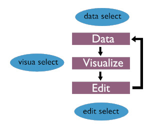
This diagram depicts Blender's most basic structure. The "data-visualize-edit" cycle is in its core, and separated from the GUI (blue) which works on three distinctive levels.
Data Select.
A user selects 'data'. That means that the user specifies the part of the 3D database he wishes to work on. This is organised in a sort of tree structure. The basic level of Blender's Data system resides in the files, which directly maps on how it's arranged in memory. Blender data can contain multiple 'scenes'; each scene consists in turn of the 3D objects, materials, animation systems and render settings.
Visual Select.
The specified data can be displayed in windows as a 3D wireframe, rendered using a Zbuffer, as buttons or as a schematic diagram. Blender has a flexible window system for this purpose, a window system that permits any type of non-overlapping and non-blocking layout.
Edit Select.
Based on the visualization chosen, the user has access to a number of tools. Editing is always performed directly on the data, not on the visualisation of the data. This seems logical, but this is where a lot of software fails in terms of interactivity and intuition. Partially, it is a speed problem; when visualizing in 3D, it can take a while before the user sees the impact of an edit command. It is also an 'inverse correction' problem: the user is only aware of the visualization, not of the actual structure that is depicted. This can be quite irritating if you attempt to do something and the results turn out to be the exact opposite of what you intended.
UI design decisions
With a 3D creation suite requiring many different but conceivable methods to make the complexity available for artists, most programs ended up with providing multiple modules, separating the workflow for artists based on tasks like 'animating' or 'material editing' or 'modeling'.
Based on our experience, as an animation studio, we didn't think this was natural nor followed the actual workflow of an art project.
Following the flow diagram as mentioned above, it was decided to:
- Base the UI on a non-overlapping non-blocking subdivision window system
- Allow each subdivided 'window' in Blender to be hooked up with any 'editor' (= visualization method), displaying any choosen type of data.
- Implement a uniform usage of hotkey and mouse commands, that don't change meaning within different contexts.
- Since it's an in-house tool, speed of usage had preference over ease of learning
The implementation of the UI was first tried with existing tools (libraries), but that failed completely because of lack of speed. The choice to create an entire new window manager, and base it all on IrisGL (predecessor of OpenGL), was one of the happy coincidences that made Blender as portable and slim as still is today.
Data structure
Most of the design time for Blender was spent on defining the right choices for which types of data belongs together, and how relationships between data is defined. With the 'implementation follows design' concept in mind, it was well understood that any design decision would both enable as restrict functionality.
Based on how we internally needed 3D for our projects, it was decided to design the data design on a high abstraction level, with these requirements:
- allowing multiple people to work together
- allowing complex animation projects to be created within 1 project (or file)
- allowing re-use of data efficiently
- allowing templates (or backdrops)
This resulted in designing a non-standard 'database', not like the traditional 'scene graph' (which was at that time perception/display based), but based on creating generic 3d 'data worlds' where you can construct as many scene graphs (displays, images, animations) as you need to.
BTW: Awareness of this concept of the data structure therefore was always a bottleneck for new users to get into Blender. :)
In Blender the data blocks are the user's building blocks: they can be copied, modified, and linked to one another as desired.
Creating a link is actually the same as indicating a relationship; this causes a block to be 'used'. This can produce an instance of a block, or to get a particular characteristic.
For example, the block type 'Object' makes a 'Mesh' block appear in the 3d scene. The Object here determines the exact location, rotation and size of the Mesh. The Mesh then only stores information on vertex locations and faces. Also, more than one Object can have a link to the same Mesh (use, create an instance). Other block types, e.g. Materials, can be linked to Meshes to obtain the block type's features.
Each of such blocks in Blender starts with an ID struct, which contains the unique name of the block and, in certain cases, a reference to the Library from which the block comes (defined for ID's linked from other blend files). The ID structure allows Blender data to be manipulated in a uniform manner, without knowledge of the actual data type.
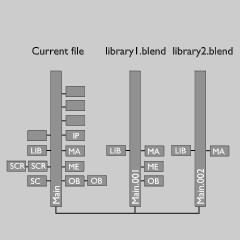
These IDs also allow Blender to arrange the files internally as a sort of file structure; as if it were a collection of directories with files.
This arrangement is also important when combining Blender files or using them as a 'Library'.
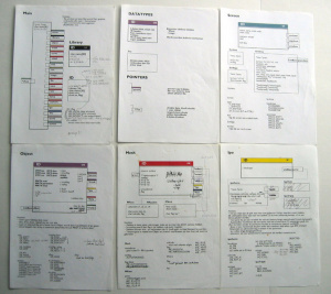
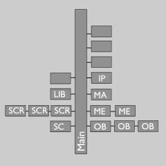
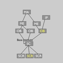
All data in Blender is stored in a Main tree, which is actually nothing more than a block of Lists. Here the data always resides, independent of how a user has linked it together. In the pictures above you can see how a 'Scene graph' was constructed from the data as available in the Main tree.
The fact that the actual data remains in the Main tree is further visualized in the Scene block. Internally it has a list of Base structs which allows a Scene to link to many Objects without removing them from the list in the Main structure.
(A Base also allows some local properties, such as layer and selection, enabling a single Object to be used by multiple Scenes with such properties different.)
When using Blender, library blocks are usually not freed themselves, but just unlinked. They remain in the Main block lists. Only when the user count is zero, such a block isn't written in a file.
In yellow here are the two main global variables, the current Screen (denoting active Scene too) and the active Object.
Data block types
All blocks as stored in the Main tree are called Library blocks (sometimes called Libdata). Library blocks all start with the ID struct:
typedef struct ID {
    void *next, *prev; /* for inserting in lists */
    struct ID *newid; /* temporal data for finding new links when copying */
    struct Library *lib; /* pointer to the optional Library */
    char name[66]; /* unique name, starting with 2 bytes identifier */
    short pad, us;
    /**
     * LIB_... flags report on status of the datablock this ID belongs
     * to.
     */
    short flag;
    int icon_id, pad2;
    IDProperty *properties;
} ID;
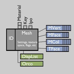
Let's take a closer look at one of the Library blocks, the Mesh. Of course such a block is actually a collection of many more blocks, either in arrays or as a List. Here we store the vertices, faces, UV texture coordinates, and so on (blue in picture). These blocks are called Direct Data. Such data is meant to be a direct part of the Mesh block, and is always written together with a Mesh or read back from the file.
Apart from this - permanent - data, there's also temporal data that can be linked to the Mesh, as for example the Display Lists. This data always is generated on the fly, not written in a file, and set at NULL when read from a file. Since all Library and Direct data resides in files too, it is important to design it compact, and leave temporal data out of it.
We now get to a very important rule in Blender's design: the usage of pointers in between blocks in Blender is restricted to pointers to Library data. This means a pointer to any Object or Mesh is allowed anywhere (in a vertex for example), but a pointer to a specific vertex cannot be stored anywhere.
This rule ensures a coherent and predictable structure, which can be used by any part of Blender code (especially for database management and files). It also defines how to make a decision when something should become Library Data; when you want it to be cross linked (re-used) everywhere within Blender.
When files get saved, the Direct Data always immediately follows its Library Data. Since saved data can contain pointers these have to be restored when reading back. The pointer rule here helps with quickly restoring the pointers to all Direct Data, since these pointers only exist within a single and relative small context. Only the pointers to Library data are stored in a global list, and all restored at once in one call (lib_link_***).
(NB: when adding game logic to Blender - Sensors, Controllers, Actuators - it was originally decided to have it reside within the Object context as Direct Data. Later on the need arose for having Sensors on Objects triggering Controllers in other Objects. This feature actually should make it Library Data, which wasn't done. A quite ugly patch for this was in a rush added to the file reading code. Until now it is still a disputed design issue; potentially the Message Actuator and Message Sensor should have been used instead.)
External Library Data
One of the design requirements was being able to import data from other files, or have it dynamically linked as a sort of template. Evaluating other 3D programs at that time (Alias, Softimage) I noticed they used the actual OS filesystem for it; creating 'project' directories with a directory tree inside and a single file for each data block. Apart from it being very clumsy and complex to maintain, I suspected it to be quite slow too. :)
Nevertheless, Blender should have at least the benefit of this approach. The usage of names for Blender data therefore closely resembles that of a filesystem, with a Blender file being a group of directories containing all of the individual files.
When using data from other files (dynamic linking), it is evident that only the Library Data blocks can be linked to. Blender then automatically reads its associated Direct Data. However, to make reading from extern files more useful, it also expands its full linked tree. For example a linked Object will also invoke reading its attached Mesh and attached Materials and Textures. Such expanded data is called "Indirect". In the interface you can recognize this with a red colored library icon. When saving to a file, such expanded (Indirect) data is not written at all. This enables the editor of the external file to change links to the Object, like adding an Ipo or add another Material.
A typical usage of this feature is dynamically linking a Scene from another file. Whatever is in that Scene will always be read.
While saving linked Library data, only its ID component is written. This ID then contains a pointer to the used "Library" (= external file), and the fact IDs have unique names then guarantees the links always restore correctly.
File saving and loading
File saving is in general just going over the the entire Main tree, and saving all blocks with users to disk as a raw binary dump. Each block saved gets a header (struct BHead) where additional information is stored, such as the original address of this block in memory.
File reading starts with reading the full file into memory. The Blender reading code then goes over all BHeads and processes Library Data and Indirect data, creating full copies. So in the end the full file can be freed from memory again. (NB: writing and reading large data chunks is to prevent disk and network overhead).
Writing dynamic linked library data
Since Blender's Main tree is just another list-able struct, it uses multiple Mains to be able to save and write dynamic linked data efficiently. This is done by the function split_main(), which creates Main trees with all data separated per the file it belongs to.
For saving, the current Main tree then can be normally processed. For the other Mains it then only saves all IDs (as type ID_ID), with a separator to denote which file it originated from (done by saving struct Library).
It then calls join_main() to merge all into a single Main tree again.
Reading dynamic linked library data
This goes a little more complex, also to allow recursion;
- While reading the data from a file, if Blender encounters a Library struct, it creates a new Main struct and remembers to store all subsequent ID_IDs there. These IDs get flagged LIB_READ.
- it then goes over all new Main trees, checking for LIB_READ flagged blocks
- if a LIB_READ block is found:
- it checks if the file containing this data was already read, if not it loads the entire file in memory and stores this in the Main struct.
- it then reads the block with the normal reading routine, linking all Direct Data to it. The new block is linked to the current Main tree and the old block removed.
- depending on block type, it calls the expand_doit() function, which forces reading more blocks like in 3.2, or it detects the data was already read correctly. Note: when such expanded data is again from another file, it just reads the ID part, links it to the correct Main and flags it LIB_READ.
- For as long as LIB_READ flagged blocks were found, it returns to step 2.
- Only in the end, it joins the Mains and restores all correct Library Data pointers.
As you can imagine, this system requires quite some pointer magic, where pointers have to be mapped to new pointers, and to new pointers again, only to end up with the correct pointer to the actual data as was allocated.
Struct-DNA (SDNA)
With choosing to save files in binary format, and knowing Blender's structure was going to be changed and expanded all the time, I thought of designing a system that would take care of all low-level version changes. This is where Blender DNA gets in the picture.
Basically, the SDNA is a compact and binary preprocessed version of the Blender include files that contain data which can be saved in files. The SDNA system can then get structure information of the contents itself, its size, element types and the names.
Each compiled Blender has such a SDNA compiled in, and in each saved .blend file an SDNA chunk is added. Additionally, for each BHead in a file it stores an index number denoting the struct type.
All of this allows changes in structs being detected and resolved. Like for example the conversion of a short to int, a char to float, an array getting more or less elements. New variables are always nicely zeroed, and removed variables are simply skipped. When doing the port to little endian systems (Blender was born big endian) it nicely allowed a good automatic conversion. Even the port to a 64 bits system (DEC Alpha) was done successfully using SDNA.
Moreover, it allows backward and upward compatibility. A Blender binary from 1997 will still nicely read files from the 2004 version, and vice versa.
The main limit is when real version changes are required. Like for example the addition of a new variable that needs to be initialized with a certain value. Or even worse, when some variables change meaning (like the physics properties for example).
