Dev:Source/GameEngine/RobotIKSolver
目次
[非表示]iTaSC
Instantaneous Task Specification using Constraints
a constraints-based IK solver for Blender 2.5
by Benoit Bolsee
This page presents iTaSC, a new Inverse Kinematics solver for Armatures that is available in Blender 2.5. The development of the algorithm and the integration in Blender was financed by the Department of Mechanical Engineering of the Katholieke Universiteit Leuven (Belgium) under the direction of Prof. Herman Bruyninckx and Joris De Schutter. iTaSC is derived from research in Robotics conducted by their team and published in the International Journal or Robotics Research Vol 26, No 5, May 2007, pp. 433-455.
This complex project wouldn't have been possible without the help and guidance of Pr. Herman Bruyninckx, and especially the support of Ruben Smits who wrote the original iTaSC code. iTaSC is integrated in Blender but the project is not finished: more constraints will be implemented and, perhaps, a new dynamic solver for armatures.
iTaSC in Blender is made of 3 modules:
- intern/itasc: the solver itself, including a subset of KDL, the open source Kinematic library developped by the KUL under the orocos project.
- source/blender/ikplugin: a plugin system that I created to support multiple IK solvers (iTaSC coexists with the old solver).
- extern/Eigen2: the BLA template library for matrix operations in iTaSC and KDL (web site).
Table of Content
General concept
IK stands for Inverse Kinematics. It is a technique that allows to automatically compute the pose of an armature such that certain control points on the armature, also called end effectors, comply with some given constraints.
IK is very important to keep animation simple: it sets part or whole of the bones automatically.
iTaSC is a new IK solver that is available in Blender 2.5, next to iksolver, the original IK solver. iTaSC is not fundamentaly different than iksolver: like iksolver, it computes the first order kinematics approximation of the armature (the Jacobian matrix), and inverts it to get the bones movements according to least square optimal. Hence, iTaSC and iksolver are not dynamic solvers; they don't take into account masses, forces and accelerations.
iTaSC differs from iksolver on several key features:
- iTaSC uses a different method to compute the Jacobian, which makes it able to handle other constraints than just end effectors position and orientation: iTaSC is a generic multi-constraint IK solver. However, this capability is not yet fully exploited in the current implementation, only 2 other types of constraints can be handled: Distance in the cartesian space, and Joint Rotation in the joint space. The first one allows maintaining an end-effector inside, at, or outside a sphere centered on a target position, the second one is the capability to control directly the rotation of a bone relative to its parent. Those interested in the mathematics can find a short description of the method used to build the Jacobian here.
- iTaSC accepts a mix of constraints, and multiple constraints per bone: the solver computes the optimal pose according to the respective weights of each constraint. This is a major improvement from the current constraint system where constraints are solved one by one in order of definition so that conflicting constraints overwrite each other.
- iTaSC has a stateful mode, which means that the pose at frame n+1 is computed from the pose at frame n. This mode is called "Simulation" because it respects the physical meaning of time: the joint velocity computed by the Jacobian solver is integrated over the interval between 2 frames (40ms at 25fps) and no more. This method leads to some (small) loss of precision on the constraints realization but has some definite advantages:
- iTaSC in Simulation mode can be considerably faster than iksolver (up to 40 times in some of my tests) since it iterates only a few times to compute the new pose.
- The movements look more natural since there is a continuity over time. In particular, there is no pose flipping during the simulation.
- iTaSC in Simulation mode can handle larger armature than iksolver. Generally, the Simulation mode leads to self-behaved armatures: armatures that moves naturally and perform tasks even with little number of constraints. However, obtaining a complete autonomous skeleton requires a lot of high level control functions that is outside the scope of iTaSC.
There is also a stateless mode, identical to iksolver operation mode, where the pose is computed from the rest pose (or animation pose) at each frame by reiterations until the constraints are met. This mode is called "Animation" since it is preferred by Animators who do not generally appreciate the dependency on the past of the Simulation mode. This mode has the same problems than iksolver in terms of performance and pose flipping but still benefits from iTaSC unique features: multiple constraint types and multiple constraints per bone.
Game Engine
Parallel to the development of the iTaSC IK solver, I've added support for external targets in the GE. Previously, only the armature constraints targetting bones of the same armature were effective in the GE; constraints targetting external objects were not affected by the game objects position and thus, had no effect in the GE. This is because the GE reuses the Blender Constraint system, which operates on Blender objects and ignores game objects.
I've added support for external targets by 'patching' the Blender objects position with the corresponding game objects position during the evaluation of the armature pose. This method is effective not only for iTaSC but also for iksolver and all the non-IK constraints. However, the iTaSC Simulation mode is best suited for the GE since it respects the real-time context of the GE, producing dynamically plausible movements. It is also much faster than iksolver and can operator large armatures in real-time.
The activation of armature constraints in the GE is done automatically but the game designer has the possibility to control the constraints to create complex interaction with the environment:
- measure residual error of constraints (only available on iTaSC IK constraint)
- activate/deactivate constraints (all constraints)
- change the weight of constraints (only for IK constraints)
- change the target of constraints (all constraints)
This is possible through logic bricks and Python scripting. Several classes have been created to give access to the armature data in Python controllers:
- BL_ArmatureConstraint: Proxy to Armature Constraint allowing to change constraints on the fly. Obtained through BL_ArmatureObject.constraints attribute.
- BL_ArmatureChannel: Proxy to Armature Pose structure, allowing to get and set bone orientation. Obtained through BL_ArmatureObject.channels attribute.
- BL_ArmatureBone: Proxy to Armature Bone structure, allowing to read rest pose information (read-only structure). Obtained through BL_ArmatureChannel.bone attribute.
The GE Python documentation can be found here.
This Python scripts shows how you can control a constraint in the GE.
 cont = GameLogic.getCurrentController()
 arm = cont.owner
 # constraints is the array of the constraints defined on the armature
 # The key index for a particular constraint is <bone_name>:<constraint_name>
 cons = arm.constraints["hand:IK"]

 # This script defines 2 states for the armature:
 # state 0 : the constraint is active (weight set to 1)
 # state 1 : the constraint is inactive (weight set to 0)
 if arm['state'] == 0:
 	# iTaSC updates lin_error with the residual metric error
 	# on the realization of the constraint
 	if cons.lin_error > 0.4:
 		# The error is much larger than 0: the target is out of reach
 		arm['state'] = 1
 		# By setting the weight to 0, the constraint is effectively
 		# disabled but the lin_error continues to be updated
 		cons.ik_weight = 0.0
 else:
 	if cons.lin_error < 0.35:
 		# The error becomes small enough to allow tracking
 		arm['state'] = 0
 		# reactivates the constraint
 		cons.ik_weight = 1.0

 # Force the GE to evaluate the pose (and thus execute the IK solver)
 # on next graphics frame.
 arm.update()
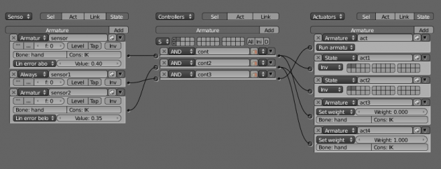
The exact same logic can be implemented in Logic Bricks:
Notice the Armature Sensor to detect error threshold on constraint and the Armature Actuator to change constraint weight and update pose.
iTaSC User Interface
This section describes the difference in the UI when iTaSC is used.
iTaSC Activation
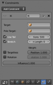
To activate iTaSC on an armature, you must first create an IK constraint on a bone. In Pose mode, select the bone that will be the end effector of the armature (generally a terminal bone), select the constraint context in the button panel and add an IK constraint.
Note the check box in the constraint header, it is a new generic feature: you can disable a constraint without deleting it or setting its weight to 0. The constraint is enabled when the check box is selected. This feature is available to all constraints and all IK solvers.
At this stage, the IK options are identical: the old IK solver is selected by default.
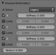
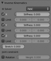
Once an IK constraint exist, the Inverse Kinematics panel appears for all bones of the IK chain.
Notice the solver selector button. Legacy stands for the old IK solver, which is selected by default. Click on the button and select iTaSC in the menu to activate iTaSC on all IK chains of the armature.
Note that the Inverse Kinematics panel shows parameters that are specific to each bone. However, the IK Solver selection is global to all bones of the armature object. If you change the solver on a bone, you change it for all the bones. The solver selection is put in this panel to remind the user that he must at least create one IK constraint to activate the IK solver.
iTaSC Constraints
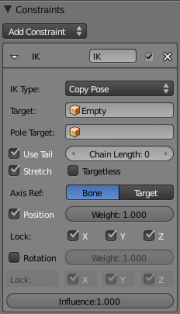
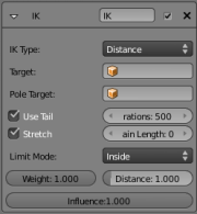
Once iTaSC solver is selected, the IK constraint panel changes a bit:
Notice the IK type selection where you can choose between two types of IK constraints: Copy Pose and Distance.
Copy Pose is equivalent to the traditional end effector position and orientation constraint: the end effector is constrained to take the position, and optionally the orientation, of a given target, which is set in the target field.
Most buttons are identical to the Legacy solver and they have the same meaning. The constraint reproduces all the features of the Legacy solver except that the influence parameter is not implemented if Pole Target is used.
The new Lock buttons allow to obtain various effect by not constraining the coordinates along certain axis. The Axis Ref selector specifies how to compute the coordinates: Bone (the default) means that the coodinates are the position and orientation of the target relative to the bone. Target means the opposite: the coordinates are the position and orientation of the tip of the bone relative to the target.
Locking a Position axis means that the coordinate along that axis is constrained to 0. When all 3 axis are locked, the constrained position is (0,0,0), which means that the end effector tends to get at the target position (regardless of the Axis Ref selector).
Unlocking a Position axis allows the coordinate to take any value along that axis. Which value depends on other constraints, joint limits, Armature structure, etc. You can influence the value but not fix it (although this could be the object of a future enhancement since iTaSC supports offset).
Locking a Rotation axis means that the coordinate of the equivalent rotation axis between the two orientations is constrained to be 0 along that axis. When all 3 axis are locked, the equivalent rotation axis is constrained to (0,0,0), which means no rotation and thus the end effector tends to take the same orientation than the target (regardless of Axis Ref Selector).
Unlocking a Rotation axis has to effect of allowing free rotation along that axis. By unlocking certain axis, you can get interesting effects:
- Bone ref, Unlock Y Pos
- Effect: The end effector points towards the target without stretching.
- Explanation: The target position is (0,Y,0) relative to the bone => the target is on the Y axis, aligned with the bone.
- Target ref, Unlock X and Y Pos
- Effect: The end effector touches the XY plane of the target (floor effect).
- Explanation: The end effector position is (X,Y,0) relative to the target => it is on the 'floor'.
- Bone ref, enable Rotation, Unlock Y Rot
- Effect: The end effector is parallel to the Y axis of the target
- Explanation: The rotation axis is (0,Y,0) which keeps the Y axis aligned.
If you choose the Distance constraint, you can specify that the end effector will stay inside, at, or outside a sphere centered on the target object with Distance as radius.
This constraint demonstrates the capabality of iTaSC to handle more than the traditional end effector position. This constraint can be used to implement obstacle avoidance behavior for the armature.
The Inverse Kinematics panel hasn't changes except for the joint constraint option. Select this option to activate a joint rotation constraint on that bone. The pose rotation computed from Action or UI interaction will be converted into a joint value and passed to the solver as target for the joint. This will give you control over the joint while the solver still tracks the other IK targets. You can use this feature to give a preferred pose for joints (e.g. rest pose) or to animate a joint angle by playing an action on it.
The weight field gives the importance of the joint rotation constraint in case all constraints cannot be achieved at the same time: the constraints with a low weight will be less respected in favor of the constraints with a high weight. For example, if you want to enforce strongly the joint rotation, set a high weight on the joint rotation constraint and a low weight on the IK constraints.
iTaSC Parameters
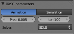
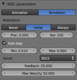
Above the Inverse Kinematics panel, you will see the iTaSC parameters panel. There are two main modes: Animation and Simulation.
In Animation mode, iTaSC operates like iksolver: it is stateless and uses the pose from Fcurves interpolation as the start pose before the IK convergence. The target velocity is ignored and the solver converges until the given precision is obtained. Still the new solver is usually faster than the old one and provides features that are inherent to iTaSC: multiple targets per bone and multiple types of constraints.
The Prec button gives the maximum variation in Blender unit of the end effector between two successive iterations at which the solver decides that a stable pose is obtained and stops the iterations. Lower values means higher precision on the end effector position.
The Iter button specifies the upper bound for the number of iterations.
The Solver buttons selects the inverse Jacobian solver that iTaSC will use.
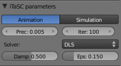
Two solvers are available: Selective Damped Least Square (SDLS) and Damped Least Square (DLS). See below a discussion on solvers and damping. If you select the DLS solver, you can tune the damping manually with the next two options.
Damp: maximum amount of damping. Smaller values means less damping, hence more velocity and better precision but also more risk of oscillation at singular pose. 0 means no damping at all.
Epsilon: range of the damping zone around singular pose. Smaller values means smaller zone of control and greater risk of passing over the singular pose, which means oscillation.
Damp and Epsilon must be tuned for each armature. You should use the smallest values that preserve stability.
The Simulation mode is the stateful mode of the solver: it estimates the targets velocity, operates in a 'true time' context, ignores rotation from keyframes (except via a joint rotation constraint) and builds up a state cache automatically.
Reiteration:
- Never: the solver starts from the rest pose and does not reiterate (converges) even for the first frame. This means that it will take a few frames to get to the target at the start of the animation.
- Initial: the solver starts from the rest pose and re-iterates until the given precision is achieved, but only on the first frame (i.e. a frame which doesn't have any previous frame in the cache). This option basically allows you to chose a different start pose than the rest pose and it is the default value. For the subsequent frames, the solver will track the target by integrating the joint velocity computed by the Jacobian solver over the time interval that the frame represents. The precision of the tracking depends on the feedback coefficient, number of substeps and velocity of the target.
- Always: the solver re-iterates on each frame until the given precision is achieved. This option destroys most of the iTaSC dynamic behavior: the maximum joint velocity and the continuity between frames is not guaranteed anymore in compensation of better precision on the end effector positions. It is an intermediate mode between Animation and real time Simulation.
Auto Step: use this option if you want to let the solver decide how many substeps should be executed for each frame. A substep is a subdivision on the time between 2 frames for which the solver resolves the IK equation and updates the joint position. More substeps means more processing but better precision on tracking the targets. The auto step algorithm estimates the optimal number of steps to get the best trade off between processing and precision. It works by estimation of the non-linearity of the pose and by limiting the amplitude of joint variation during a substep. It can be configured with next 2 parameters:
Min: proposed minimum substep duration (in second). The auto step algorithm may decide to reduce the substep further based on joint velocity.
Max: maximum substep duration (in second). The auto step algorthm will not allow substep longer than this value.
Num Steps: if Auto Step is disabled, you can choose a fixed number of substeps with this parameter. Substep should not be longer than 10ms, which means Num Steps=4 for 25 fps animation. If the armature seems unstable (vibrates) between frames, you can improve the stability by increasing the number of steps.
Feedback: coefficient on end effector position error to set corrective joint velocity. The time constant of the error correction is the inverse of the this value. However, this parameter has little effect on the dynamic of the armature since the algorithm evaluates the target velocity in any case. Setting this parameter to 0 means 'opening the loop': the solver tracks the velocity but not the position; the error will accumulate rapidly. Setting this value too high means an excessive amount of correction and risk of instability. The value should be in the range 20-100. Default value is 20, which means that tracking errors are corrected in a typical time of 100-200ms. The feedback coefficient is the reason why the armature continues to move slightly in Simulation mode even if the target has stopped moving: the residual error is progressively suppressed frame after frame.
Max Velocity: Indicative maximum joint velocity in radiant per second. This parameter has an important effect on the armature dynamic. Smaller value will cause the armature to move slowly and lag behind if the targets are moving rapidly. You can simulate an inertia by setting this parameter to a low value.
Troubleshooting
This section explains some of the internal mechanism of iTaSC. It is important to understand them if you experience problems with iTaSC and wonder what is going on. This is applicable only to the Simulation mode where you have a lot of control over the algorithm. In Animation mode, iTaSC takes all the decisions automatically.
State Caching
In simulation mode, iTaSC uses a flexible cache to store the state of the simulation along the time axis so that the solver can retrieve the armature pose and estimate the target velocity even if the frame counter is going backward or changing randomly.
The term "flexible" means that the cache is built automatically and incrementally (no need to bake) and is tolerant to non sequential time change forward or backward. However, the exact and reproducable simulation is only obtained when you run the animation sequentially from the start. After that you can bring the frame counter backward and scrutinate the simulation frame by frame.
How it works:
The pose cache is attached to an IK-tree representing the system to solve: armatures and constraints. The iTaSC plugin extracts from the Blender scene the parts that must be resolved and builds the IK-tree. The IK-tree stays in memory as long as no element is changed in the scene that affects it (adding or removing a constraint, changing the bones, etc). The pose cache keeps tracks of all the variables of the system: state values, input values (=target object position) and desired constraint values.
When iTaSC is requested to give the current pose of an armature, it fetches the IK-tree (rebuilds it if necessary), digs into the cache to find the pose at the start of the frame (=the pose at the end of the previous frame), retrieves the input values from the scene, estimates the velocity and runs the solver to compute the new pose. If the previous frame is not in the cache, it takes the most recent frame, and if no frame at all is in the cache, it falls back on the rest pose.
After the solver iterations (and reiterations if configured so), the new pose and input values are put in the cache. If they are identical to the values that were already in the cache for that frame, the cache is left unchanged. If they are different, it means that the content of the cache for any future frame is also incorrect and those frames are removed from the cache.
Interaction with UI
If you change a target position in the 3D view, Blender walks down the dependency graph and sends a cache clear request to all dependent objects, which includes the armature since it depends on the target. This is currently implemented in iTaSC by clearing the entire cache.
This creates the nasty side effect that iTaSC looses its stateful nature while you are changing a target position interactively: you'll get flipping if you cross 'hot' points, etc.
This is because iTaSC doesn't know what is the starting frame of the animation and considers that any frame that doesn't have a previous position in the cache is a starting frame. In this case, the algorithm converges to the IK targets, starting from the rest pose, and reiterates until the armature doesn't move anymore (see Reiteration option in iTaSC Parameters panel).
This is the normal behavior for the actual starting frame but it's not desirable at any other frame. So if you are at some frame and do an action that causes the cache to be cleared, you'll see the armature taking a pose that is most probably not the correct one. You can only see the correct pose if you run the animation from the start => the initial pose will be set correctly and the cache will build up from there.
There is no simple solution to this problem. I am evaluating several options and I hope to find a good compromise that will provide an intuitive interactivity to the user.
Velocity Estimation
In Simulation mode, iTaSC uses the target velocity to achieve better precision on the tracking. As Blender does not specify the velocity directly, it must be evaluated.
When creating an animation, the time information is available through the frame counter. At 25 fps, the time interval between two frames is 40ms. iTaSC assumes constant velocity during a frame interval and passes this velocity to the solver.
In the BGE, the real time is available through the system clock and the time only goes forward. There is no need for caching and the velocity can be derived from the real time. The time between two frame is variable, but usually in the order of 1/60 second.
Sub-Stepping
In Simulation mode, non-linearities in the armature or target trajectory can lead to loss of precision in the tracking and oscillations in the armature pose:
- when the target moves quickly, the gap to cross in one frame is so large that the first order approximation of the Jacobian is not valid anymore.
- when the armature is close to a singular pose, the first order approximation is not valid anymore and leads to excessive corrections: the end effector moves eratically.
The instability near singular pose is solved by proper damping. See below the discussion on Jacobian solver and damping.
The instability due to excessive target velocity can be fixed by sub-stepping: by subdividing the 40ms interval in 4 intervals of 10ms and solving the joint velocity for each sub-interval, the armature stays in the linear zone for each sub-step and the precision of the tracking is much better.
However, in many cases it is unnecessary to subdivide the interval (because the armature is moving slowly) and in other cases, 4 intervals is not enough (because the armature is moving rapidly or is in strong non-linear configuration). This is why an auto-step algorithm is provided that takes into account the non-linearities and maximum velocity.
If you see the armature shaking when playing the animation, you may need to increase the number of sub-steps, either by reducing the Max parameter of the Auto-step algorithm, or increasing the number of steps in the Fixed-Step method.
If the shaking persists, you may need to choose the DLS Jacobian solver and tune the Damping parameters as explain below.
Damping
iTaSC computes the joint velocities by inverting the Jacobian. iTaSC uses the traditional pseudo inverse, which is known to give incorrect velocities when the armature is near a singular pose. The armature is expected to take a singular pose when the target is out of reach: the armature will stretch out as much as possible in the direction of the target.
Before taking the singular pose, the armature must go through a 'nearly' singular pose where the movements towards the target are still possible but very limited. This situation creates a lot of non-linearity in the armature kinematics so that the first order approximation given by the Jacobian is not valid anymore. Singularity can be detected by low numerical Singular values during the inversion process. Low Singular values leads to high velocity and excessive movements after integration.
This can be avoided by damping the low Singular values, i.e. reducing their influence in the final joint velocities. There is unfortunately no direct correspondance between a particular Singular value and a particular level of non-linearity.
iTaSC provides two solvers to address this problem: the Selective Damped Least Square (SDLS) and Damped Least Square (DLS) solvers.
The SDLS solver computes the damping automatically by estimating the level of 'cancellation' in the armature kinematics. This method works well with the Copy Pose constraint but has the inconvenient of damping more than necessary around the singular pose, which means slower movements. Of course, this is only noticeable in Simulation mode. If you want more reactivity and more precision, you can use the DLS solver which allows manual tuning of the damping.
The Damp parameter controls how strongly a Singular value is damped when it gets closer to 0. High values means less movements towards the singular pose and greater number of iterations to get to the singular pose. Low value means faster movement but greater risk of over-correction and oscillation. You should choose the lowest value that preserves stability.
The Epsilon parameter controls the high bound of Singular value below which damping is applied according to Damp parameter. The value that correctly represents the 'dangerous' zone depends on the armature. There is currently no visual tool to help choosing this parameter but one possibility would be to change the color of the outline of the armature (or some other visual tip) based on the number of Singular values that are below this threshold: the more values below the threshold, the more 'extreme' is the singularity of the pose from the point of vue of the solver. By matching the solver 'point of vue' with his point of vue, the user could tune the parameter more easily (the user can easily see if the pose is singular in the 3D view).
Notes:
- The SDLS solver is inoperant if you use the Distance constraint. You must use the DLS solver if you are going to have a singular pose in your animation with the Distance constraint.
- Both solvers perform well if you don't have singular pose.
Extending iTaSC
The capabilities of iTaSC can be extended by implementing new types of constraint. A constraint can only be added to iTaSC when its virtual armature is clearly defined. If you are unfamiliar with iTaSC principles, read this page first and if it is still unclear, read the original article in the International Journal of Robotics Research, Vol. 26, No. 5, May 2007, pp. 433-455.
Before adding a new constraint, you may consider reusing the existing constraints in a different way. The CopyPose constraint for example is not fully exploited in the current implementation: iTaSC allows to set offsets but this feature is not implemented in the UI. By adding the necessary fields in the Blender structures and the necessary UI buttons and conversion code in the iTaSC plugin, one could provide programmatic control of the end effector position and orientation relative to target.
You can also create virtual unconstrained object in iTaSC. Currently, all unconstrained objects correspond to real Blender objects (those specified in the Target field of the IK constraint). But if you have a function that produces a space reference, you can map it to an unconstrained object and pass the space reference to iTaSC in the callback function. Then using the ordinary CopyPose constraint, you can control the armature to track that virtual object.
All these features are supported in iTaSC, you just needs to add the necessary UI and plugin code.
If after these considerations you still think you need a new constraint and you have the design of the constraint armature in mind, you will find the step by step instructions here:.
Developer's guide for adding constraint in iTaSC
Good luck
