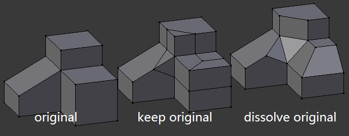
Dev:Source/Modeling/BMesh/Suggestions
Started this wiki page to organize proposals for functionality which is currently being made on blenderartist threads which isnt so helpful. --Ideasman42 13:36, 18 February 2012 (CET)(Sign)
To wiki contributors: please try to maintain the alphabetical ordering when inserting new suggestions. --s12a
目次
[非表示]- 1 Bevel (Edge/Vertex)
- 2 Bevel (Face)
- 3 Boolean Tools
- 4 Chamfer
- 5 Drop Tool
- 6 Edge improvements
- 7 Edge/Vertex Extrude
- 8 Extrude corner-awareness
- 9 Face Extrude
- 10 Fillet
- 11 Insert Vertex
- 12 Inset / Offset
- 13 Knife
- 14 Loft
- 15 Loop Cut/Edge Slide
- 16 Manipulator
- 17 Ngon holes
- 18 Remove Doubles - merge vertices to edges
- 19 Selection Changes
- 20 Subdivide Changes
- 21 Vertex Slide
- 22 Edit Mesh Modifier
- 23 Mesh Cleanup Tools
Bevel (Edge/Vertex)
Basis for inclusion
Not only it is critical to mechanic modeling or CAD, but it also can be a very very handy topology tool in organic modeling --trvoldemort
Expected Behavior
When beveling anything, whether a face, edge or vertex the tool should likely work by activating and then adjusting with the mouse movement, like most other tools. The precies settings can be fine tuned via the operator panel. By adjusting with the mouse you save unnecessary mouse movement and allow for very quick editing without needing to access the tool bar or menus. --Jonathan Williamson
User opinion 1
This is what users would normally expect from a simple, "single cut" bevel --s12a:
User opinion 2
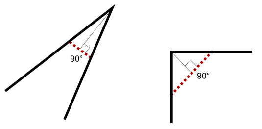
[Referring to the image in "User opinion 1"] The maximum the dashed line goes is until one face disappears completely. In that point the bevel can't continue. Look the image below, when the bevel makes disappear the shortest face that is the far the bevel can go, so bevel would have its maximum in the image on the right. Bevel acts on selected edges so bevel stops for all of them when in one edge the face disappears, or we would have different bevels for each selected edge obviously. The created faces the bevel tool creates can then be subdivided and these new subdivided faces can be arranged in an arc way that can be outwards or inwards and another slider would graduate from 0 to 100 being 0 flat and 100 a bezier arc formed by three points: two in the two exterior edges of the bevel and one in the original edge before the beveling.
I was reading the bevel discussion and seems all the tools will have a hard time with edges owned for more than two faces. Perhaps the best solution would be that the toolds do nothing with such edges and only work with edges owned by 1 or two faces. 3dsmax for example don't lets you build a mesh where an edge is owned by more than two faces.
But what if the face is not "square". Look the upper face now bevel don't make it disappear completely. But bevel must stop also in the same place. So Instead of "when one face disappears" I want it to change to "bevel stops when one edge disappears".
And an example of maximum bevel in these three edges. Bevel can't continue because one edge disappears.
And this is the actual wrong bevel tool in bmesh: 1) Beveled width is different along the bevel 2) There is the creation of a triangle on the vertex that has 5 edges. I think it is better to collapse the segment in the triangle to only one vertex as in my image above --Bao2
User opinion 3
(trvoldemort) I'm planning to make a concept tool that harmoniously merge "Bevel Vertices/Edges", "Extrude Vertices/Edges" and "Fillet". Still WIP.
Parameters of bevel operator:
- Edges Selection: User select the vertice and edges to be beveled.
- Cutting Mode:
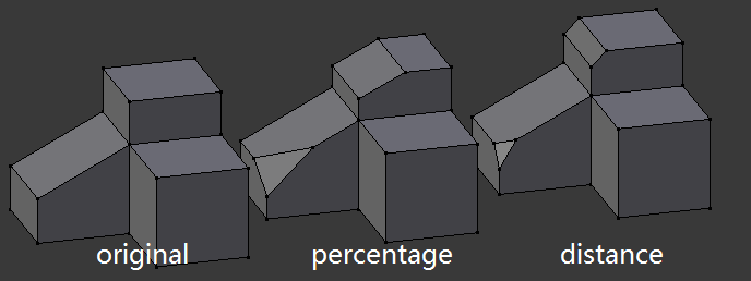
- Percentage: Bevel by cutting adjacent edges by a percentage.
- Distance: Bevel by pushing selected egdes a certain distance along the bisector of adjacent faces.
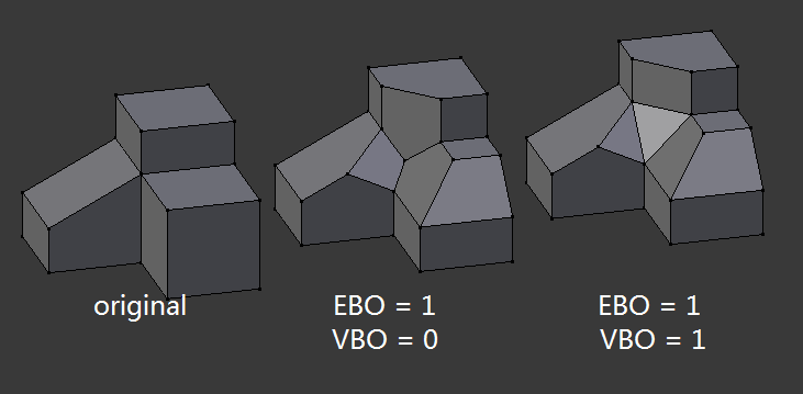
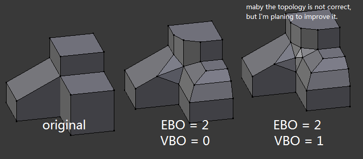
- Edge bevel order (1-inf): Number of cuts.
- Vertex bevel order (1-EBO): Importance is demonstrated in a picture below.
- Section Outline:
- Outside 1/4 Circle.
- Inside 1/4 Circle.
- Outside 3/4 Circle.
- Inside 3/4 Circle.
- Custom Curve Object.
- Whether to keep the original edges:
UI suggestions
Different bevel strategies
Three different modes of operation could be included to suit different uses:
- The distance between the original vertex and the center of the beveled edge
- The distance between the original vertex and the end of the beveled edge
- The length of the beveled edge
1) and 2) differ increasingly as the edge angle increases.
Multicut bevel
Bevels with an arbitrary number of cuts (3, 5, 6, 7, ...) , and not only of a power of two (1, 2, 4, 8 ...) / recursive. Common in engineering designs.
Practical Examples
GSculpt
GSculpt is an "orphaned" open source software that has a comprehensive set of polygon modelling tools. Cutting tools are especially great. Here is the bevel behaviour of this program (Link to external video) --demohero
Wings3D
wings3d has a good bevel tool and is open source too. it could maybe save a lot of time to take a look at how their solution work. --Inspir3dArt
Their solution only works for closed meshes. Wings3D doesn't allow open ones. Granted, beveled geometry is closed most of the time, but at the very least special cases would have to be added. --MadMinstrel
XSI
I found XSI 4.0 bevel tools example from youtube. There are many options. Link to video on Youtube --demohero
I think that video explains it much better than I would do. However since I already made this example, I'll post it.
Settings are on the right of the objects. First one on the right of the original object is plain vanilla bevel with 'manage collisions' on which welds vertices that would go over the edge length into the object. On the bottom of the original object is the same but with 'uniform mitering' on which should guarantee that the edges are of equal length. On the right of the bottom image is a fancy version that has 'rounding' on (multiple bevel) and a curve to the bevel with tangency and a extrapolation amount (meaning that new verts move on their normals by that amount). Finally on the top right is the side faces beveled with automatic hard edges on the contour of the bevel. Link to external picture showing an example of how Bevel works on XSI --el_diablo
Bevel (Face)
Basis for inclusion
Fundamental modeling tool for hard-surfaced modeling, in particular for architectural visualization.
Options
- Amount/depth - depth of bevel
- Recursion - sets the number of cuts in bevel (can be set via scroll wheel, similar to loop cuts)
- Curve - allows you to bulge the bevel in or out
Suggested Workflow
- Select face(s) to bevel
- Press W > Bevel
- Move mouse to adjust bevel amount (constrain to increments with Ctrl )
- LMB
 to confirm
 - Finetune via operator panel if necessary
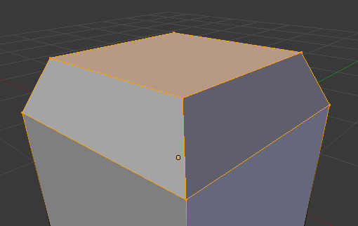
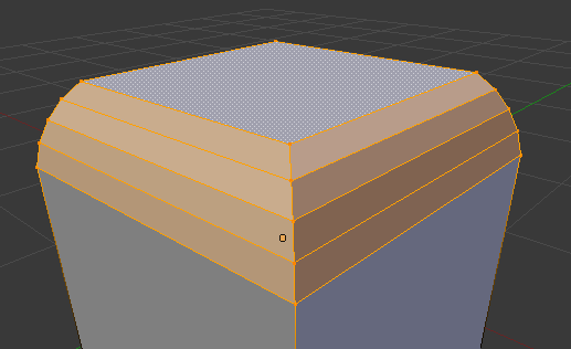
Face bevel with no recursion and no curve
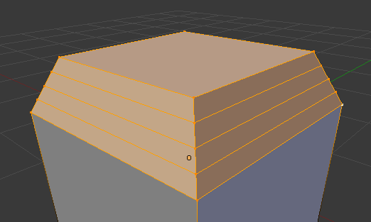
Face bevel with recursion of 3 and no curve
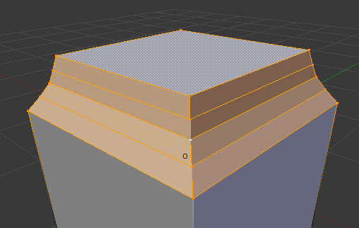
Face bevel with recursion of 3 and curved in
Face bevel with recursion of 3 and curved out
-- Jonathan Williamson
Boolean Tools
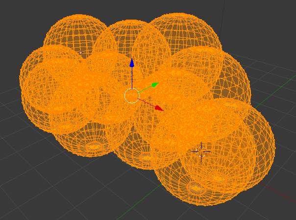
Quick Boolean modeling inside edit mode. Say we've created a bunch of spheres, and overlapped them. We then want to remove all internal faces, but this is difficult to do. Create a Boolean modifier on one, targeting the second; apply, and then add one to that targeting the next, etc. That's working at O(n). Here's our sphere example joined into one object, but still with internal verts.
We should be able to have a Boolean tool presenting the Boolean types of the modifier. It would allow creating a union, intersection, or difference of all selected objects to the active object. They would be merged into one mesh.
I recommend a button in the toolbar while in object mode, and access with the unused shortcut Alt-J. When either is pressed a menu will show at the cursor asking which of the three types it should use.
Chamfer
(Closed for duplication)
Drop Tool
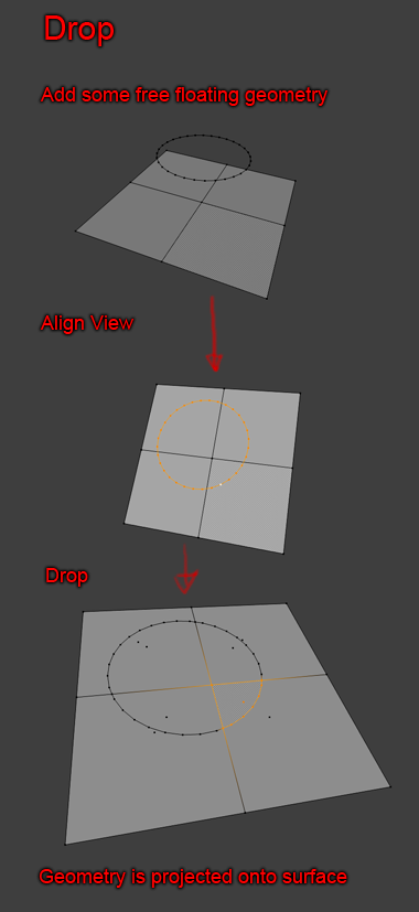
Useful for cutting holes and indentations into surfaces. --MadMinstrel
Snapping on surface is already able to project vertices like in first step. Blender is just missing last step : retopology of Quads into Ngons using Circle's edges.--Zeauro
The "Drop Tool" (on the new BMesh suggestions wiki) looks similar to what is mentioned in [Link to Vimeo video]. At 22.30 and 29.15 it's being utilized, very useful! Some snap option is enabled in 3ds Max. --Guran
Is this solved by the Knife Project tool? --GreenJello
Edge improvements
Simple operations on the edges, as implemented in this Add-On: -- mandragora (via Witold Jaworski)
I wish the internal edges issue was fixed, but that was in trunk before the merge too and otherwise Remesh works fine. Booleans still triangulate faces, but also work fine otherwise. --MadMinstrel
Edge/Vertex Extrude
Options
Toggle between the two below options by holding down Alt
- Extrude on Normal: Act as the current extrude tool by extruding the current selection along the normal.
- Free Extrude: Extrude selection freely, regardless of element type, unless otherwise specified.
-- Jonathan Williamson
Suggested Workflow
TODO
There should be a way to disable/togge (in user preferences) auto constraining to axes when extruding an edge - it really irritates when doing more organic modelling. --PLyczkowski
Extrude corner-awareness
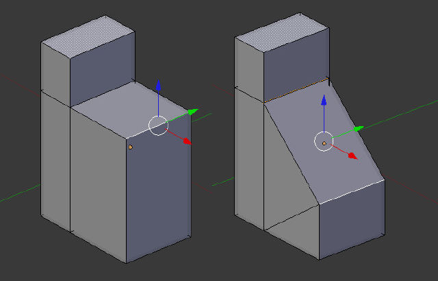
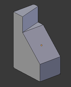
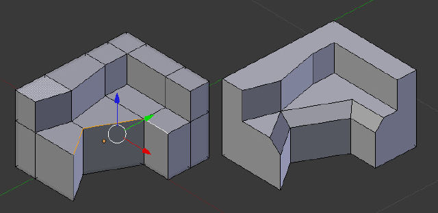
The current behavior for corners is rarely the desired one and to do this with the current tools requires quite a lot of steps. Sketchup has a similar tool, and it's extremely useful. This could go to either extrude or inset, or both. It should remain optional and non-default. --MadMinstrel
Face Extrude
Extrude on Normal
Act as the current extrude tool with faces by extruding the current selection along the averaged normal or normal of the active face.
Free Extrude
Extrude selection freely, regardless of element type, unless otherwise specified.
Additional options
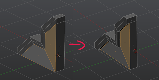
1. Twisting extruded faces by a given angle around the extrusion direction -- mandragora (via Witold Jaworski)
2. Allow to Pin some vertices - it would allow to obtain in single operation an effect like on this picture:
 -- mandragora (via Witold Jaworski)
Separate Extrude
Separate Extrudes - if I extrude a group of polygons, I have an option to extrude them as a group - or - as separate faces moving through every face's normal (In Maya there's a check box made just for this case). --PrinterKiller
Fillet
Edge Fillet
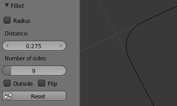
From zmj100's edge tools. They do not currently support ngons or faces at all (only edge outlines), but work beautifully:
As with other tools I feel the fillet should work by activating the tool and then adjusting with the mouse.
Suggested Workflow
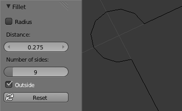
Select two or more connected edges to fillet, then press CtrlE > Fillet and move mouse to adjust the size of the fillet. Moving in a negative direction less than 0 will create a inside fillet, moving in a positive direction greater than 0 will create a normal fillet. After clicking the LMB ![]() to confirm the fillet you may then adjust the number of vertices in the fillet via the Operator panel or set it as an Outside fillet. --Jonathan Williamson
to confirm the fillet you may then adjust the number of vertices in the fillet via the Operator panel or set it as an Outside fillet. --Jonathan Williamson
Regular
Outside
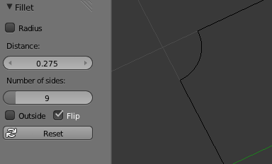
Flip
Face Fillet
TODO
Insert Vertex
A simple insert vertex tool would be useful. Click an edge->new vertex appears under mouse with Grab on. Move mouse to move into position, confirm (left click) to place, cancel(right click) to leave it where it originally appeared. Alternatively it could work like LoopCut, but that means you have to move it into place in a separate operation and can't snap to stuff other than percentage along the edge.
Using subdivide is cumbersome and too many clicks. If you're tweaking vertices, you need to select the adjacent ones (which might be entirely off-screen), or switch into edge mode and then back to vert mode again. --MadMinstrel
Inset / Offset
Basis for inclusion
Inset should be made into a simple and quick tool. It should only be applied to a string of line segments (whether closed/open or co-planar/non-planar is valid). A common misunderstanding is that Inset is applied to faces. No, it's not. A face is a particular case of a segment string. --trvoldemort
A great example of the inset tool is the Inset Extrude add-on for Blender 2.62 and back:
http://wiki.blender.org/index.php/Extensions:2.6/Py/Scripts/Modeling/Inset-Extrude
It works very well (in most cases) and the workflow is good by using the "I" key to activate and then move the mouse to adjust. --Jonathan Williamson
Modes of operation
zmj100 edge tools include two modes of operation from which bmesh core tools could take ideas:
Regular / Classic
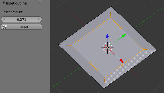
Negative inset values create an inset polygon, positive an offset polygon.
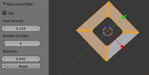
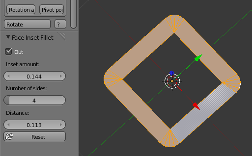
Face Inset Fillet
A hybrid between Inset and Fillet. A similar bmesh tool (even better with hole support) wouldn't create the nasty triangles on the rounded edges visible below.
Normal
Outside
== Practical Examples
Wings 3d
Inset options in Wings3d. MMB inset options - Link to Youtube video --kakachiex2
Inset LMB WINGS inset tools have the option to bump while inseting - Link to Youtube --kakachiex2
Knife
UI Suggestions
At the moment there is no feedback in the header on what hotkeys/actions are available when the knife tool (K) is activated. Hold Ctrl = snap to middle of the edge, ⇧ Shift = no snapping, angle constraint (C) etc. --Guran
It should be possible to undo the last step (click) when the knife tool is activated. --Guran
I don't like the options of snapping. It's either both edges and vertices (which means it will be hard to do a cut very close to a vertices without snapping to it) or no snapping at all (⇧ Shift) (which means that it wont snap to the edge you want to cut to, having no snapping at all is not what you want in most situations). --Guran.
I think that an additional option "Snap the Last Only" would resolve the problem described by Guran. It can be used with one of the knife snap options. Currently, when the Ctrl is pressed (i.e. "Midpoint" snapping) a single straight cut across multiple edges divides each of them in the middle. "Snap the Last Only" option (availabe under the F6 key), would apply the midpoint snap only to the last edge. (All previous edges would be divided by the straight segment, between the initial knife position and midpoint on the last edge) -- mandragora (via Witold Jaworski)
An option to snap to the middle of a face might be useful. --Guran
Just to not miss the feature which was present in Blender 2.4x: restrict the cut to selected edges, only. It was reported in bugtracker (id=28716) and discussed with Howard T. Probably on the TODO list -- Witold Jaworski
User opinion 1
(trvoldemort)
Operation Parameters:
- Snap Mode: (be sure we can always change it during cutting)
- CtrlAlt Vertices.
- Ctrl Edges. (WheelUp
 /WheelDown
  switch between Mid/Trisect/Quadrasect Point/)
 - CtrlAlt⇧ Shift Faces. ( Yes ... we do need that. To be able to snap to barycenter is great. For example, better T loop making.)
- Ctrl⇧ Shift Increment. ( Handy for perfectly horizontal/vertical/diagonal cutting.)
- Cutting Power:
- Cut Selected.
- Cut Visible.
- Cut Everything™. (Sometimes I need to give the model a super straight cut that penetrates every thing like cutting a complex model by half.)
Other suggestions:
- Important! Be able to snap views using numpad during cutting.
- Maybe ⇧ Shift for accurate mode as usual?
- additional option "Disable Ngons": disabling generation of the ngons during the cut. (This means creation of additional triangular or quadrilateral faces, as in Blender 2.49); -- mandragora (via Witold Jaworski)
- @mandragora: I think this should be separated from knife. IMHO, knife should be the tool for manually change topology, it should be highly predictable like drawing on paper. So there should be an independent tool for trianglarize n-gons. --trvoldemort
Added functionality: Swiss Knife
I'm using the Super Knife a lot in a bmesh build of Blender I downloaded form GraphicAll.org. Often, however, I feel it could be enhanced by making it not only cut through existing faces, but also create new geometry (vertices/edges) when using it on empty areas. It would save some time and make certain operations more precise and quicker rather than having to extrude at a later time and them resuming the cutting work. Of course, since this is generally an unwanted behavior, it could be toggable. Or it could be an entirely different tool instead. --s12a
Suggestion to expand Angle Constraint functionality
I'm using Knife tool quite often now and found that I would like to use the Angle Constraint with wider angle choices. It can be at least with a min. step 5. It would be really good to have an ability to set the step in Preferences. It's very common in CAD and CG 3d editors and often usable. Angle numbers are actual from 0.5 degree (maybe I'm wrong here) to 90 degrees with any increments. For UI I see this like a radio button (to enable custom angles functionality) and number fields: the minimum step, the maximum step, the increment (>min. step) and the major angles. Major angles (multiple by the increment) means that when you want to see all 5x or 10x angles (or other specific angles) with slightly other color or a bit "magnetized" to them (when you move the mouse and it stops near major angles). This functionality will be very handy for mechanical and architectural designs because it speed ups the workflow and allow to exclude a frequent usage of the Protractor tool (when it's necessary).
Loft
Basis for inclusion
Connect a series of edge loops (in order) with the least distortion or other requirements (should be highly customizable). --trvoldemort
Loop Cut/Edge Slide
Non Prop Lenght/Percentage (P) and "flip control side" (F) from Blender 2.49 is missing. --Guran
Non Proportional Mode for loopcut/edgeslide would be very useful to have back. Especially for subsurf hard surface modelling where you have to add supporting edge loops everywhere. --uvwxyz
Link to 2.4x wiki about Edge Slide
Also missing from 2.49 is loop cut smoothing. You could define how much smoothing a cut got. This is very useful for increasing mesh density on parts that have some degree of curvature to them. --tyrant monkey
Loop Selecting
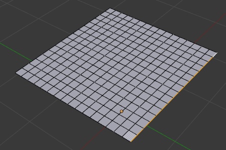
When a plane is subdivided, loop selecting it's edges selects the whole plane boundary. It would be helpful if there was also an option to select only the loop, not the whole boundary:
A way to select a partial loop - after selecting two edges next to each other in a loop, an option to select more and less edges in that loop.
I found the two above features useful when modeling in modo.--PLyczkowski
Selecting partial loop between selected edges - Select one edge, and than select the, say, fourth edge after that with double click - and all the edges between those two are being selected either. Time consuming in Maya -- PrinterKiller
It is already there in blender. Select one edge. Then, Ctrl + select mouse button on second edge. -> edges in between are selected.--Zeauro
Manipulator
Ngon holes
Actually, my #1 wish for the mesh system is Ngon holes in Ngon faces. --Freemind
Full support to holes would allow total freedom and very clean meshes after boolean operations. --s12a
@Freemind: Agree! Holes are the obvious missing slice of pie in polygon system. The only problem is that Catmull-Clark is not suitable for holes. But they are great for fast sketches, and can be manually/automatically converted into hole-free polygons. --trvoldemort
Remove Doubles - merge vertices to edges
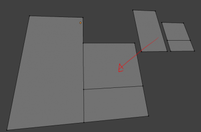
It would be a good idea to allow merging vertices into edges if they occupy the same space or are very close, as an option. It comes up a lot with hard surface modelling and it takes a lot of steps to do manually. --MadMinstrel
Selection Changes
Subdivide Changes
Provide a complete interface for Catmull-Clark algorithm. Not just edge crease. But the weight of every vertex, edge and face should be changable. So that it can theoretically approch any NURBS curve. --trvoldemort
Vertex Slide
Curvature-aware slide
I used it numerous times in Softimage, only thing its implementation is missing is taking into consideration subsurf curvature. And there are tools that do just that in other packages. To explain more, for example when I do automotive modeling i tweak and slide arbitrary vertices with proportional (fallof) tool to get them in a better position. Without slide you quickly introduce bumps (actually you introduce them with slide also, but not so easily as without). --el_diablo
- Oh. So that was sliding on the surface. I wasn't listening to the audio, so I thought he was just moving vertices around. --Madminstrel
- Now I agree with you. Talking about subsurf curvature (or more precisely, NURBS curvature), I think Blender's current so-called edge slide is also a primitive one, all it does is a batch of so-called vertex slide. A "slide" operation, if we define it "change the low-poly model but minimize the influence on its sub-d generated high-poly version", Blender should definitely consider NURBS curvature for a better result.
- A curvature-aware slide is like this -- trvoldemort:
- I don't get it. Why if I want to slide that edge is good that instead the image in the middle (that I expect) must I be given the one on the right (I would be shouting names on the developper if that were the case). I want it to slide to the image in the center always. Is there some critical need of such a thing in modeling mechanical objects perhaps? --Bao2
- Let's say you have a subsurfed cylinder and want to slide a loop (length-wise), but preserve the circular shape. The curvature-aware slide will do that for you and minimize pinching. This should also be added to Loop Cut for adding new loops but preserving subsurf shape. It's useful for when you're modelling something like, say, a gun with a round barrel. --MadMinstrel
- Well, well, a curvature-aware slide! I've been thinking about coding such a tool. In fact one can make a more generic smoothing or relaxing tool that moves vertices according to the normals of the neighboring vertices. Then, edge slide would simply run the generic tool during transform. It's a bit differrent from a curvature tool though. A curvature-aware slide relies on the fact that we have two 2 "external" edges connected to each vertex of the edge loop so a curvature calculation is possible (we can fit a quadratic surface on these points). For a more general tool (using more than 2 other points) I think a linear combination of nearby vertices/normals can be used. --Psy-Fi
Edit Mesh Modifier
It would be nice to be able to edit a mesh with a modifier working on it, without applying the modifier. This way the non-destructive nature of the modifiers is preserved.
For instance if you are working on a model with a mirror modifier, you can add the 'Edit Mesh' modifier after the mirror modifier to add some asymmetry. But you can still make symmetrical changes by editing the base mesh.
The UI could be very simple, you don't need any settings (i can't think of required ones) just a 'edit button' button to edit the mesh. If you hit 'TAB' to go into edit-mode, you get a pop-up menu and you can choose tho edit the base mesh or one of the modifiers (if you have multiple ones working on your mesh).
- EDIT: There are some very good objections to this functionality in this thread: http://blenderartists.org/forum/showthread.php?208555-Edit-poly-modifier. So maybe this is not such a good idea.
Mesh Cleanup Tools
Plans for 2.69 - tools to clean mesh geometry where manually fixing is tedious.
Planerize
Makes faces flat.
Motivation
When you have distorted geometry, either created by accident or from imported data.
Solution
A tool which can flatten faces.
- With a partial selection a vertex will be placed so it doesn't cause distortion in surrounding non triangle faces.
- With a fully selected face we can simply project the vertices of the face along the faces normal to flatten it.
Parameters
- Influence: so you can control how flat the faces will be.
Face-Angle-Split
splits faces along their most stressed angle.
Motivation
With non planer faces sometimes you want to split them without triangulating.
Solution
Given a limiting angle, split ngons until they contain no 2 halves that exceed the given angle (Split until flat).
Parameters
- Angle Limit: Angle beyond which splitting isn't done.
Face-Concave-Split
Makes all ngons concave.
Motivation
Concave ngons may have troubles filling but you don't always want to triangulate them.
Solution
Split ngons until all faces are convex.
Fill Holes
Fills in faces from selected geometry.
Motivation
With some imported models you can have gaps in a surface, manually filling and assigning UVs etc, is a hassle.
Solution
A tool witch detects loops in boundary edges (and optionally a wire edge) and fills them in with faces, copying attributes.
Parameters
- Loop Size: How many sides to fill in, so you can select the entire mesh and not fill in larger holes.
- Option to copy attributes (UV's, V-Colors, Materials etc)
Make Contiguous Normals
Flips normals so they match surrounding geometry.
Motivation
Sometimes meshes have badly set normals, yet re-calculating isnt working as you want/expect.
Solution
Flip faces whos normal matches less then half of the surrounding faces normals.
Parameters
- Measurement Method: Test flipping by face count or by length of flipped faces.
Dissolve Overlap
A remove doubles that takes vertices meeting edges (Better name?)
Motivation
Some models (epspecially from CAD applications) will have multiple surfaces that look continuous but don't actually have joined topology.
Solution
To use a kind of remove-doubles tool that can detect vertices on on edges.
Parameters
- Distance threshold: As with remove doubles, distance for merging.
Note
This could be extended to dissolve overlapping faces too.
Remove Doubles (Non manifold)
Add an option to remove doubles that only ever removes doubles which result in manifold geometry.
Motivation
Remove doubles is useful but can result in odd cases too, where vertices from disconnected surfaces meet. So the assurance geometry will still be non-manifold after remove doubles is useful.
Solution
Optionally - limit remove doubles to only produce non-manifold geometry (no 3 face edges for eg)
