Doc:2.6/Manual/Constraints/Common Interface
Page status (reviewing guidelines)
Text
examples
Images
examples
|
Constraints Common Interface
As with modifiers, an object (or bone, see the rigging chapter for details) can use several constraints at once. Hence, these constraints are organized in a stack which controls their order of evaluation (from top to bottom).
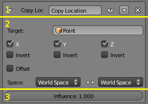
All constraints share a common basic interface, packed up in a sort of sub-panel, that is split into three parts:
- The header, gathering most common settings.
- The constraint’s specific settings.
- The influence and animation controls (the Rigid Body Joint constraints have no influence setting).
Constraints Header
The header of a constraint “sub-panel” is the same for all. From left to right, you have:
- A small arrow
- This control allows you to show/hide the constraint’s settings.
- The constraint type
- This is just static text showing you what this constraint is…
- The name field
- Here you can give your constraint a more meaningful name than the default one.
- This control has another important purpose: it turns red when the constraint is not functional (as in A constraint header). As most constraints need a second “target” object to work (see below), when just added, they are in “red state”, as Blender cannot guess which object or bone to use as target. This can also happen when you choose an invalid set of settings, e.g. with a Track To constraint of which the To and Up vectors are both set to the same axis.
- As noted above, constraints in “red state” are ignored during the stack evaluation.
- The “up”/“down” buttons
- As seen above, these allow you to move a constraint up/down in the stack.
- The “X” control
- As seen above, this will delete (remove from the stack) the constraint.
Constraints Settings
The constraints settings area is of course specific to each constraint type. However, there are two points that are common to many constraints, so we will detail them here.
The target
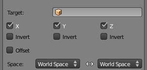
Most constraints need another “target” object or bone to “guide” them. You select which by selecting its name in the Target field. Except for a few cases, you can use any type of object (camera, mesh, empty…); its object origin will be the target point.
When you type in the OB field a mesh or lattice name, a second Vertex Group field appears just below. If you leave it empty, the mesh or lattice will be used as a standard object target. But if you enter in this Vertex Group field the name of one of the mesh’s or lattice’s vertex groups, then the constraint will use the median point of this vertex group as target.
Similarly, if you type in the OB field an armature name, a second Bone field appears just below. If you enter in it the name of one of the armature’s bones, then the constraint will use this bone’s root as target.
In some constraints, when you use a bone as target, another Head/Tail numeric field will also appear, that allows you to select where along the bone the target point will lay, from root (0.0) to tip (1.0) (remember that currently, in Blender UI, bones’ roots are called “heads”, and bones’ tips, “tails”…).
The Constraint Space (Space)
For many constraints you can choose in which space it is evaluated/applied. In the Space drop-down lists, the right side one is the space that the owner is evaluated in (Owner Space). When such a constraint uses a target, you can also choose in which space the target is evaluated (Target Space). The Target Space drop-down list is on the left side. Both lists have the same options, depending on whether the element (owner or target) is a regular object, or a bone:
- Local Space
- The object's properties are evaluated in its own local space, i.e. based on its rest position (without taking into account its parents’ transformations in its chain, or its armature object’s transformation).
- Local With Parent (bones only)
- The bone properties are evaluated in its own local space, including the transformations due to a possible parent relationship (i.e. due to the chain’s transformations above the bone).
- Pose Space (bones only)
- The bone properties are evaluated in the armature object local space (i.e. independently from the armature transformations in Object mode). Hence, if the armature object has null transformations, Pose Space will have the same effect as World Space…
- Local (Without Parent) Space (objects only)
- The object properties are evaluated in its own local space, without the transformations due to a possible parent relationship.
- World Space (default setting)
- Here the object’s or bone’s properties are evaluated in the global coordinate system. This is the easiest to understand and most natural behavior, as it always uses the “visual” transform properties (i.e. as you see them in the 3D views).
Understanding the Constraint Space effects is not really easy (unless you are a geometry genius…). The best thing to do is to experiment with their different combinations, using e.g. two empties (as they materialize clearly their axes), and a Copy Rotation constraint (as rotations are the most demonstrative transformations, to visualize the various spaces specificities…).
Influence
At the bottom of nearly all constraints, you have the Influence slider, which controls the influence of the constraint on its owner. As you might expect, 0.0 means that the constraint has no effect, and 1.0 means that the constraint has full effect. Using in-between values, you can have several constraints all working together on the same owner’s properties. Note that if a constraint has a full influence on a given property, all other constraints above in the stack working on that same property will have no effect at all.
But the best thing with influence is that you can animate it with an Fcurve – see the constraints page of the animation chapter for more details about this.

