Doc:2.6/Manual/Modeling/Meshes/Selecting
Page status (reviewing guidelines)
Page reviewed and in good shape |
Selecting Mesh Components
There are many ways to select elements, and it depends on what Mesh Select Mode you are in as to what selection tools are available. First we will go through these modes and after that a look is taken at basic selection tools.
Selection Modes
Select Mode Header Widgets
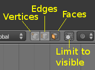
In Edit mode there are three different selection modes. You can enter the different modes by selecting one of the three buttons in the toolbar.
Using the buttons you can also use more than one selection mode at a time by ⇧ ShiftLMB ![]() clicking the buttons.
clicking the buttons.
- Vertices
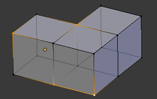
- Selected vertices are drawn in orange, unselected vertices in black, and the active or last selected vertex in white.
- Edges
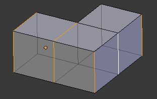
- In this mode the vertices are not drawn. Instead the selected edges are drawn in orange, unselected edges black, and the active or last selected edge in white.
- Faces
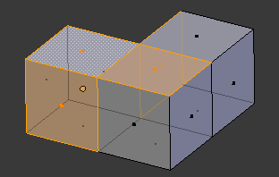
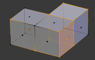
- In this mode the faces are drawn with a selection point in the middle which is used for selecting a face. Selected faces and their selection point are drawn in orange, unselected faces are drawn in black, and the active or last selected face is highlighted in white.
Almost all modification tools are available in all three mesh selection modes. So you can Rotate, Scale, Extrude, etc. in all modes. Of course rotating and scaling a single vertex will not do anything useful without setting the pivot point to another location, so some tools are more or less applicable in some modes.
Note
The three selection mode buttons are only visible in Edit mode. The colors of selected, unselected and active components depend entirely on the current theme. Black, orange and white are from the default theme.
|
Select Mode Pop-up
Mode: Edit mode
Hotkey: Ctrl⇆ Tab
You can also choose a selection mode with the pop-up menu
- Select Mode » Vertices
- Press Ctrl⇆ Tab and select Vertices from the pop-up menu, or press Ctrl⇆ Tab1.
- Select Mode » Edges
- Press Ctrl⇆ Tab and select Edges from the pop-up menu, or press Ctrl⇆ Tab2.
- Select Mode » Faces
- Press Ctrl⇆ Tab and select Faces from the pop-up menu, or press Ctrl⇆ Tab3.
Switching select mode
When switching modes in an “ascendant” way (i.e. from simpler to more complex), from Vertices to Edges and from Edges to Faces, the selected parts will still be selected if they form a complete element in the new mode.
For example, if all four edges in a face are selected, switching from Edges mode to Faces mode will keep the face selected. All selected parts that do not form a complete set in the new mode will be unselected.
Hence, switching in a “descendant” way (i.e. from more complex to simpler), all elements defining the “high-level” element (like a face) will be selected (the four vertices or edges of a quadrangle, for example).
By holding Ctrl when selecting a higher selection mode, all elements touching the current selection will be added, even if the selection does not form a complete higher element.
See (Vertices mode example), (Edges mode example), (Faces mode example) and (Mixed mode example) for examples of the different modes.
Selection Tools
The select menu in edit mode contains tools for selecting components. These are described in more detail in the following pages.
- Border Select
- Enables a rectangular region for selection
- Circle Select
- Enables a circular shaped region for selection
- (De)select All A
- Select all or none of the mesh components.
- Invert Selection CtrlI
- Selects all components that are not selected, and deselect currently selected components.
- Select Random
- Selects a random group of vertices, edges, or faces, based on a percentage value.
- Checker Deselect
- Deselect alternating faces, to create a checker like pattern.
- Select Sharp Edges
- This option will select all edges that are between two faces, forming an angle less than the user-specified value. The lower this angle limit, the sharper the selected edges will be. At 180°, all “manifold” (see below) edges will be selected.
- Linked Flat Faces (Ctrl⇧ ShiftAltF)
- Select connected faces based on a threshold of the angle between them. This is useful for selecting faces that are planar.
- Interior Faces
- Select faces where all edges have more than 2 faces.
- Side of Active
- Selects all data on the mesh in a single axis
- Select Faces by Sides
- Selects all faces that have a specified number of edges.
- Select Non Manifold (Ctrl⇧ ShiftAltM)
- Selects vertices that are not completely bound by geometry, including border edges, floating edges, and orphan vertices. Only available in Vertex mode.
- Loose
- Select all vertices or edges that do not form part of a face.
- Similar
- Select components based on how similar certain properties are to it.
- More CtrlNum+
- Propagates selection by adding components that are adjacent to selected elements.
- Less CtrlNum-
- Deselects components that form the bounds of the current selection
- Mirror
- Select mesh items at the mirrored location.
- Linked CtrlL
- Selects all components that are connected to the current selection.
- Shortest Path
- Selects the shortest vertex path between two selected vertices or edges
- Edge Loop
- Selects a loop of edges from a selected edge
- Edge Ring
- Selects edges parallel to a selected edge in the same ring of faces
- Loop Inner-Region
- Converts a closed selection of edges to the region of faces it encloses
- Boundary Loop
- Converts a selection of faces to the ring of edges enclosing it
