Doc:2.6/Manual/Rigging/Armatures/Visualization
Armature visualization
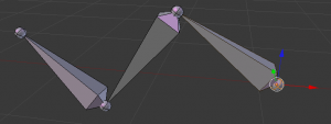
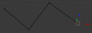
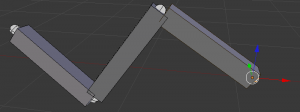
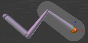
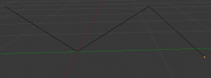
We have 5 basic bone visualization: Octahedral, Stick, B-Bone, Envelope and Wire:
Display Panel
Mode: Object, Edit and Pose modes
Panel: Display Object Data context
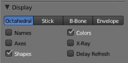
But let’s first see some general visualization properties of armatures, found in the Display panel of the Object data context.
Bone types
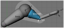
Octahedral bone
This is the default visualization, well suited for most of editing tasks. It materializes:
- The bone root (“big” end) and tip (“small” end).
- The bone “size” (its thickness is proportional to its length).
- The bone roll (as it has a square section).
Stick bone
This is the simplest and most non-intrusive visualization. It just materializes bones by sticks of constant (and small) thickness, so it gives you no information about root and tip, nor bone size or roll angle.
B-Bone bone
This visualization shows the curves of “smooth” multi-segmented bones; see the bone page for details.
Envelope bone
This visualization materializes the bone deformation influence. More on this in the bone page.
Attributes
- Names
- When enabled, the name of each bone is drawn.
- Colors
- This is only relevant for Pose mode, and is described in detail there.
- Axes
- When enabled, the (local) axes of each bone are drawn (only relevant for Edit and Pose modes).
- X-Ray
- When enabled, the bones of the armature will always be drawn on top of the solid objects (meshes, surfaces, …) – i.e. they will always be visible and selectable (this is the same option as the one found in the Display panel of the Object data context. Very useful when not in Wireframe mode.
- Shapes
- When enabled, the default standard bone shape is replaced, in Object and Pose modes, by the shape of a chosen object (see below for details).
- Delay Refresh
- When enabled, the bone doesn't deform its children when manipulating the bone in pose mode.
Shaped Bones
Mode: Object and Pose modes
Panel: Display panel from Bone context.
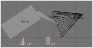
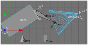
Blender allows you to give to each bone of an armature a specific shape (in Object and Pose modes), using another object as “template”. First of all, you have to enable the Shapes button (Armature panel).
Attributes
- Wireframe
- When enabled, bone is displayed in wireframe mode regardles of the viewport drawing mode. Useful for non-obstructive custom bone chains.
- Hide
- Bone is not visible when not in Edit mode.
- Custom Shape
- Object that defines the custom shape of the selected bone.
- Custom At
- Bone that defines the display transform of this shape bone
To assign a custom shape to a bone, you have to:
- Switch to Pose mode (Ctrl⇆ Tab).
- Select the relevant bone (RMB
 click on it).
 - Go to the Display panel Custom Shape field and select the 3D object previously created in the scene; in this example we are using a cube and a cone. Tou can optionally set the At field to another bone.
Note that:
- These shapes will never be rendered – like any bone, they are only visible in 3D views.
- Even if any type of object seems to be accepted by the OB field (meshes, curves, even metas…), only meshes really work – all other types just make the bone invisible; nothing is drawn…
- The center of the shape object will be at the root of the bone (see the bone page for root/tip).
- The object properties of the shape are ignored (i.e. if you make a parallelepiped out of a cube by modifying its dimensions in Object mode, you’ll still have a cube shaped bone…).
- The “along bone” axis is the Y one, and the shape object is always scaled so that one Blender Unit stretches along the whole bone length.
- If you need to remove the custom shape of the bone, just right click in the Custom Shape field and select Reset to default value in the popup menu.
So to summarize all this, you should use meshes as shape objects, with their center at their lower-Y end, and an overall Y length of 1.0 BU.
Armature Layers
Mode: Object, Edit and Pose modes
Panel: Skeleton panel, Object data context
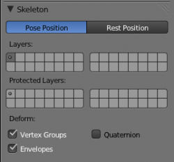
Each armature has 32 “Armature layers” which allow you to organize your armature by “regrouping” sets of bones into layers; this works similar to scene layers (those containing your objects). You can then “move” a bone to a given layer, hide or show one or several layers, etc.
Showing/hiding bone layers
Only bones in active layers will be visible/editable – but they will always be effective (i.e move objects or deform geometry), whether in an active layer or not. To (de)activate a layer, you have several options, depending in which mode you are in:
- In all modes, use the row of small buttons at the top of the Display Options group, Armature panel. If you want to enable/disable several layers at once, as usual, hold ⇧ Shift while clicking…
- In Edit and Pose modes, you can also do this from the 3D Views, either by using the menu (Armature » Switch Armature Layers or Pose » Switch Armature Layers), or the ⇧ ShiftM shortcut, to display a small pop-up dialog containing the same buttons as described above (here again, you can use ⇧ ShiftLMB
 clicks to (de)select several layers at once).
Protected Layers
You can lock a given bone layer for all proxies of your armature, i.e. all bones in this layer won’t be editable. To do so, in the Skeleton panel, CtrlLMB ![]() click on the relevant button, the layer lock will be enabled.
click on the relevant button, the layer lock will be enabled.
Protected layers in proxy are restored to proxy settings on file reload and undo.
Bone Layers
Mode: Object, Edit and Pose modes
Panel: Relations panel Bone context
Moving bones between layers
Obviously, you have to be in Edit or Pose modes to move bones between layers – note that as with objects, bones can lay in several layers at once, just use the usual ⇧ ShiftLMB ![]() clicks… First of all, you have to select the chosen bone(s)!
clicks… First of all, you have to select the chosen bone(s)!
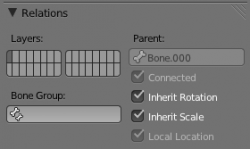
- In the Button window, use the “layer buttons” of each selected bone “sub-panel” (Armature Bones panel) to control in which layer(s) it lays.
- In the 3D View window, use the menu (Armature » Move Bone To Layer or Pose » Move Bone To Layer) or hit M to show the usual pop-up layers dialog. Note that this way, you assign the same layers to all selected bones.
Hiding Bones
Mode: Edit and Pose modes
Panel: Display panel, Bone context
You do not have to use bone layers to show/hide some bones. As with objects, vertices or control points, you can use the H key:
- H will hide the selected bone(s).
- ⇧ ShiftH will hide all bones but the selected one(s).
- AltH will show all hidden bones.
You can also use the Hide check button of the Display panel, Bone context).
Note that hidden bones are specific to a mode – i.e. you can hide some bones in Edit mode, they will still be visible in Pose mode, and vice-versa. Hidden bone in Pose mode are also invisible in Object mode. And in Edit mode, the bone to hide must be fully selected, not just his root or tip…
