Extensions:2.6/Py/Scripts/NeuroMorph/Centerline Tools
| UI location | View3D » Centerline Tools | ||
|---|---|---|---|
| Version | 1.1.0 | Author(s) | Anne Jorstad |
| Blender | 2.78 | License | GPL |
| File name | NeuroMorph_Centerline_Processing.py |
|---|---|
| Current version download | https://github.com/NeuroMorph-EPFL/NeuroMorph/tree/master/NeuroMorph_CenterLines_CrossSections |
目次
- 1 NeuroMorph Links
- 2 Overview
- 3 Description
- 3.1 Clean and Export Mesh for Processing in VMTK
- 3.2 Load Centerline File from VMTK
- 3.3 Get Cross-sectional Surface Areas
- 3.4 Get Maximum Radius of each Cross Section
- 3.5 Project Spheres to Centerline
- 3.6 Project Surface Areas to Centerline
- 3.7 Export Data
- 3.8 Detect Boutons (Experimental)
- 3.9 Extract Axon Regions Between Points
- 4 VMTK Instructions for Computing Centerlines
- 5 A Method for Manually Creating or Extending Centerlines
NeuroMorph Links
Blender Wiki Home
Code on GitHub
For more information please visit the NeuroMorph project website.
Overview
This module processes centerlines of tubular structures, such as axons, as generated by the Vascular Modeling Toolkit (VMTK), and performs calculations using these centerlines in Blender, including constructing cross-sectional surfaces and calculating densities of nearby objects by projecting them onto the centerline. Tools are also provided for detecting bouton swellings.
VMTK is only able to generate centerlines of "clean" meshes. This add-on provides a tool to help clean meshes in Blender, but meshes with significant non-manifold self-intersecting regions may require non-trivial manual adjustments. Alternately, an approximate centerline may be constructed by hand, and the functions of this add-on will still work.
Description
Clean and Export Mesh for Processing in VMTK
- Delete all children of mesh to be processed (see NeuroMorph_Parent_Child_Tools add-on).
- Select the tubular mesh and click Clean Mesh for Processing. This will delete any problematic non-manifold regions from the mesh, and fill in the holes with smooth surfaces. Such regions often result from the mesh generation process, but can prevent VMTK from processing.
- Modified vertices are returned in a selected state (highlighted orange in Edit mode), so that you can easily see where modifications have been made.
- If the function deletes any large pieces of the mesh, you will have to undo and clean those regions of the mesh by hand, then try this button again until it works.
- If this function deletes large pieces of the mesh, it is very likely that VMTK also will not be able to process the mesh as it is, and you will have to clean the mesh by hand enough so that this function is able to run without deleting any important parts of the mesh.
- Select the mesh and click Write Mesh to vtp. This will bring up a window where you can choose where to save the vtp file. Make sure it is called "mesh.vtp".
- See VMTK Instructions for Computing Centerlines section below for instructions on how to get the centerline using VMTK.
Load Centerline File from VMTK
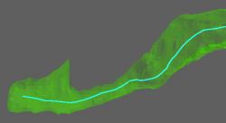
Click Load Centerline from vtp, navigate to the "centerline.vtp" file, click "Load centerline from vtp file".
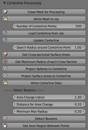
- This function uses the Number of Centerline Points to extract that many near-evenly-spaced points from the centerline generated by VMTK, as long as this value is less than the number of vertices in the original centerline. This value defines how many vertex points will be used in the calculations to follow. The number of centerline points of an already loaded object will not be changed simply by changing this value; a new centerline object must be loaded by clicking Load Centerline from vtp again.
- If the loaded centerline does not span the entire length of the mesh, you have two options:
- Clean the mesh further and re-process in VMTK.
- Extend the centerline by hand using standard Blender functionality, making sure that the centerline points are roughly evenly spaced. See A Method for Manually Creating or Extending Centerlines section below. Once the desired centerline is achieved, Update Centerline must be clicked.
Get Cross-sectional Surface Areas
Select a mesh and its corresponding centerline object, then click Get Cross-sectional Surface Areas. This will create a cross sectional surface of the mesh at every centerline vertex.
- This function uses the Search Radius around Centerline Point to determine the size of the planes it generates perpendicular to the centerline, whose intersections with the mesh result in the cross-sectional areas. This value should generally be at least twice the expected maximum radius of the tubular mesh. When this value is too small, irregular geometry can result in the intersecting plane not reaching all the way from the centerline to the mesh in every direction, and the function will fail. Using a value that is too large will significantly increase processing time.
Get Maximum Radius of each Cross Section
Select a centerline object whose cross sections have already been computed via the above button, then click Get Maximum Radius of each Cross Section. This will calculate the maximum radius of each cross section object, and store the values internally, to be provided on export.
- The radius is measured from the centroid of the cross section (the average location of all its vertices) to each of its vertices separately. The location of the intersection of the centerline and the cross section does not affect this calculation. The maximum radius is defined as the largest of these radius distances.
Project Spheres to Centerline
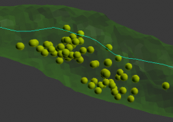
Select a mesh object (assumed to be a number of possibly overlapping but distinct spherical meshes joined into a single object, where the spheres may represent objects such as vesicles) and a centerline object, then click Project Spheres to Centerline. This will project the center of each individual sphere to the closest centerline vertex, and count the number of spheres projected to each vertex.
- This function only considers the centroid of each distinct object of the input mesh object. Non-spherical objects can also be processed. Distinct objects of the input mesh are determined using Blender's "Separate - By loose parts" function.
Project Surface Areas to Centerline
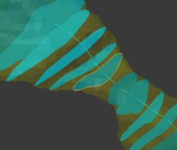
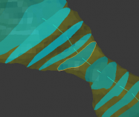
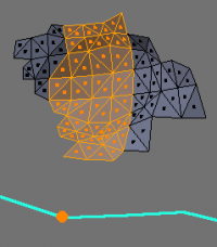
Select a mesh object (assumed to be a number of possibly distinct surface meshes joined into a single object) and a centerline object, then click Project Surface Areas to Centerline. This will project the center of each individual surface polygon to the closest centerline vertex, and sum up the areas of the polygons projected to each vertex for a total projected surface area per vertex. The image on the right shows the individual polygons on a surface that would be projected to the highlighted centerline vertex.
Export Data
Clicking Write Centerline Data will export all the data that has been calculated to a csv file. Data that may exist for each centerline vertex:
- Length from endpoint along the centerline (always provided)
- Minimum radius of mesh (comes from VMTK, will be lost if centerline has been adjusted by hand)
- Surface area of cross section
- Maximum radius of mesh
- Number of spheres projected
- Sum of surface areas projected
Detect Boutons (Experimental)
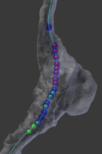
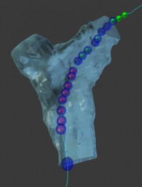
The Detect Boutons button places colored spheres on centerline vertices whose cross-sections meet certain geometric criteria that might indicate the presence of a bouton (a swelling of the tubular structure).
- Increasing/decreasing cross-sectional surface area: If the cross-sectional surface area is increasing or decreasing by at least a factor of Area Change (ratio) (eg 1.3 in the example below) over a distance of Distance for Area Change (eg 0.2 in the example below) along the axon, then red or green spheres are added to the centerline. (The direction of increase is defined from the lowest to the highest centerline index.)
- A green sphere indicates that somewhere over the next 0.2 distance along the centerline, there is a vertex whose cross-sectional surface area is at least 1.3 times larger than the surface area at the vertex with the green sphere. If there are two green spheres in a row, this condition is true for each of them independently; the spheres do not mark the entire region of area increase, they only mark where the condition starts.
- A red sphere indicates that somewhere over the next 0.2 distance along the centerline, there is a vertex whose cross-sectional surface area is at least 1.3 times smaller.
- Large cross-sectional radius: If the maximum radius of the cross section at a vertex is greater than Minimum Max Radius (eg 0.2), then a blue sphere is placed at the centerline vertex. The radius is measured from the centroid of the cross section (the average location of all its vertices) to each of its vertices separately, and the maximum radius is defined as the largest of these distances.
Extract Axon Regions Between Points
Extract a sub-region of an axon by selecting two points from the centerline to bound it. The volume of the region can then be calculated using the NeuroMorph Measurement Tools. Select either two centerline vertices from Edit mode, or two centerline spheres as created with the Detect Boutons button, then click Extract Axon Regions Between Points. This will create a new object that is a sub-region of the axon to which the centerline belongs, bounded by the cross sections from the two input points.
- This tool uses the Search Radius around Centerline Point to determine the size of the planes it generates perpendicular to the centerline. These planes are then joined into a box, and the the tool extracts the region of the axon mesh that is inside this box. For particularly large boutons, the search radius value may need to be increased.
VMTK Instructions for Computing Centerlines
- Install VMTK as instructed on their website.
- From the command line, navigate to the folder containing your "mesh.vtp" file, and run the following script:
vmtkcenterlines -ifile mesh.vtp -ofile tmp.vtp; vmtksurfacewriter -mode ascii -ifile tmp.vtp -ofile centerline.vtp
- Once the mesh loads in the VMTK viewer,
- Position the mouse at one end point of the mesh, hit space, then hit q
- Position the mouse at the other end point, hit space, then hit q
- Wait for the file to be created: can take between a couple seconds to several minutes
- Most of the VMTK text output can be ignored, unless it says "Target not reached" at the end before the final "Done executing vmtkcenterlines" report, in which case the output is not correct.
- A file "centerline.vtp" will be created, which can be read back into Blender using the tools above. The temporary file "tmp.vtp" can be deleted or ignored.
Note: if the above command does not work, try running it as two separate commands:
 vmtkcenterlines -ifile mesh.vtp -ofile tmp.vtp
 vmtksurfacewriter -mode ascii -ifile tmp.vtp -ofile centerline.vtp
Complete instructions can be found on the VMTK Computing Centerlines website.
A Method for Manually Creating or Extending Centerlines
- Given at least one line segment, click and drag end point to the desired final locations (end points of the mesh).
- Use Mesh Tools » Subdivide to get more vertices; adjust their locations as necessary.
- Use Mesh Tools » Remove Doubles with a non-zero "Merge Distance" to achieve the vertex spacing of your choice.
- Once the desired centerline is achieved, Update Centerline must be clicked.
Note about centerline precision
Extreme precision of centerline vertices is not required. As long as the centerline runs near the middle of the mesh with near-evenly spaced vertices, the tools in this add-on will function sufficiently well. The centerline must always be completely in the interior of the mesh.
|
