「Doc:2.6/Tutorials/Modeling/Surfaces/Skinning」の版間の差分
(Created page with "=Skinning= {{Note|1=Note|2=This tutorial assumes you have read the Curves page.}} Skinning is the fine art of defining a surface using two or...") |
細 (1版 をインポートしました) |
(相違点なし)
| |
2018年6月29日 (金) 05:56時点における最新版
Skinning
Note
This tutorial assumes you have read the Curves page.
|
Skinning is the fine art of defining a surface using two or more profiles. In Blender you do so by preparing as many curves of the the desired shape and then converting them to a single NURBS surface.
As an example we will create the hull of a sailboat.
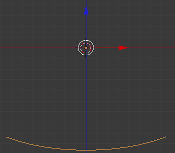
In front view (1 NumPad), add a Surface Curve by ⇧ ShiftA » Add Object Menu » Add Surface » NURBS Curve. Be sure to add a Surface NURBS curve and not a Bézier or standard NURBS curve or later stages of the tutorial will not work.
Rotate the Surface by 180 degrees around the x-axis to match the view orientation (RX180).
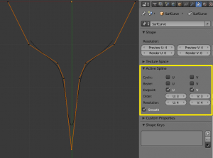
Give the curve the shape of the middle cross section of the boat, by adding vertices as needed with the Subdivide W action. You may also wish to toggle on the Active Spline Endpoints for both U and V. The Active Spline Endpoints option can be found in the Object Data panel of the Properties window. From here you can also Toggle the Smooth option which will smooth the faces.
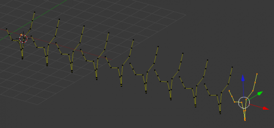
Now duplicate (⇧ ShiftD) the curve as many times as necessary. Adjust the curves to match the various sections of the ship at different points along its length. To this end, blueprints help a lot. You can load a blueprint on the background (as we did for the logo design in this chapter) to prepare all the cross section profiles.
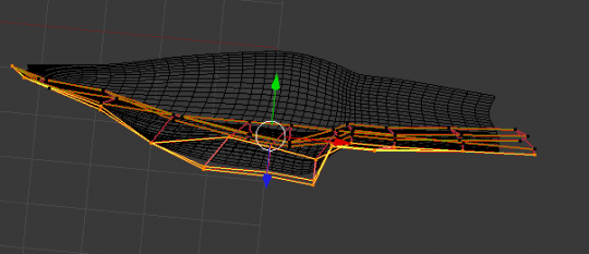
Edit the location of the control points to match the contours of a ship's hull. Note that the surface we’ll produce will be smoothed from one profile to the next. To create abrupt changes you would need to place profiles quite close to each other as seen by the image below.
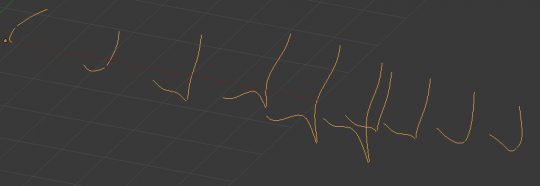
Select all the control points with A; then press F. The profiles should be “skinned” and converted to a surface.
In some cases (i.e. when joining only two curves) the resulting surface may NOT be displayed after you press F. So you need to toggle Endpoint U/V options on the Curve Tools panel to correct this issue.
Tweak the surface if necessary by moving the control points. The image to the left shows a shaded view. You may need to increase the resolution for both U and V to obtain a better shape. This can be found in the Shape panel of the Object Data context.
The only limitation to this otherwise very powerful technique is that all profiles must exhibit the same number of control points. This is why it is a good idea to model the most complex cross section first, duplicate it and then move control points as needed.
