「Doc:2.6/Manual/Composite Nodes/Types/Convertor」の版間の差分
(→Composite Convertor Nodes) |
細 (1版 をインポートしました) |
(相違点なし)
| |
2018年6月29日 (金) 04:44時点における最新版
Page status (reviewing guidelines)
Copy
This page is a copy of the same page in 2.4 manual, need to be updated
|
Composite Convertor Nodes
As the name implies, these nodes convert the colors or other properties of various data (e.g. images) in some way. They also split out or re-combine the different color channels that make up an image, allowing you to work on each channel independently. Various color channel arrangements are supported, including traditional RGB and HSV formats, and the newest High Definition Media Interface (HDMI) formats.
ColorRamp Node
The ColorRamp Node is used for mapping values to colors with the use of a gradient. It works exactly the same way as a colorband for textures and materials, using the Factor value as a slider or index to the color ramp shown, and outputting a color value and an alpha value from the output sockets.
By default, the ColorRamp is added to the node map with two colors at opposite ends of the spectrum. A completely black black is on the left (Black as shown in the swatch with an Alpha value of 1.00) and a whitewash white is on the right. To select a color, LMB ![]() click on the thin vertical line/band within the colorband. The example picture shows the black color selected, as it is highlighted white. The settings for the color are shown above the colorband as (left to right): color swatch, Alpha setting, and interpolation type.
click on the thin vertical line/band within the colorband. The example picture shows the black color selected, as it is highlighted white. The settings for the color are shown above the colorband as (left to right): color swatch, Alpha setting, and interpolation type.
To change the hue of the selected color in the colorband, LMB ![]() click on the swatch, and use the popup color picker control to select a new color. Press ↵ Enter to set that color.
click on the swatch, and use the popup color picker control to select a new color. Press ↵ Enter to set that color.
To add colors, hold Ctrl down and CtrlLMB ![]() click inside the gradient. Edit colors by clicking on the rectangular color swatch, which pops up a color-editing dialog. Drag the gray slider to edit Alpha values. Note that you can use textures for masks (or to simulate the old "Emit" functionality) by connecting the alpha output to the factor input of an RGB mixer.
click inside the gradient. Edit colors by clicking on the rectangular color swatch, which pops up a color-editing dialog. Drag the gray slider to edit Alpha values. Note that you can use textures for masks (or to simulate the old "Emit" functionality) by connecting the alpha output to the factor input of an RGB mixer.
To delete a color from the colorband, select it and press the Delete button.
When using multiple colors, you can control how they transition from one to another through an interpolation mixer. Use the interpolation buttons to control how the colors should band together: Ease, Cardinal, Linear, or Spline.
Use the A: button to define the Alpha value of the selected color for each color in the range.
Using ColorRamp to create an Alpha Mask
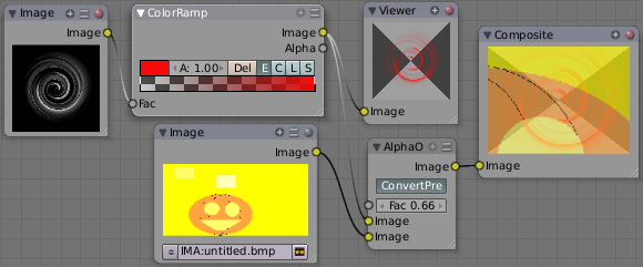
A powerful but often overlooked feature of the ColorRamp is to create an Alpha Mask, or a mask that is overlaid on top of another image, and, like a mask, allows some of the background to show through. The example map below shows how to use the Color Ramp node to do this:
In the map above, a black and white swirl image, which is lacking an alpha channel, is fed into the ColorRamp node as a Factor. (Technically, we should have converted the image to a value using the RGB-to-BW node, buy hey, this works just as well since we are using a BW image as input.)
We have set the ColorRamp node to a purely transparent color on the left end of the spectrum, and a fully Red color on the right. As seen in the viewer, the ColorRamp node puts out a mask that is fully transparent where the image is black. Black is zero, so ColorRamp uses the 'color' at the left end of the spectrum, which we have set to transparent. The ColorRamp image is fully red and opaque where the image is white (1.00).
We verify that the output image mask is indeed transparent by overlaying it on top of a pumpkin image. For fun, we made that AlphaOver output image 0.66 transparent so that we can, in the future, overlay the image on a flashing white background to simulate a scary scene with lighting flashes.
Using ColorRamp to Colorize an Image
The real power of ColorRamp is that multiple colors can be added to the color spectrum. This example compositing map takes a boring BW image and makes it a flaming swirl!
In this example, we have mapped the shades of gray in the input image to three colors, blue, yellow, and red, all fully opaque (Alpha of 1.00). Where the image is black, ColorRamp substitutes blue, the currently selected color. Where it is some shade of gray, ColorRamp chooses a corresponding color from the spectrum (bluish, yellow, to reddish). Where the image is fully white, ColorRamp chooses red.
RGB to BW Node
This node converts an RGB input and outputs a greyscale image.
Set Alpha Node
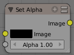
This node adds an alpha channel to a picture. Some image formats, such as JPEG, do not support an alpha channel. In order to overlay a JPEG image on top of a background, you must add an alpha channel to it using this node.
The Image input socket is optional. If an input image is not supplied, the base color shown in the swatch will be used. To change the color, LMB ![]() click the swatch and use the color-picker control to choose or specify a color you want.
click the swatch and use the color-picker control to choose or specify a color you want.
The amount of Alpha (1.00 being totally opaque and 0.00 being totally transparent) can be set for the whole picture using the input field. Additionally, the Alpha factor can be set by feeding its socket.
Note that this is not, and is not intended to be, a general-purpose solution to the problem of compositing an image that doesn't contain Alpha information. You might wish to use "Chroma Keying" or "Difference Keying" (as discussed elsewhere) if you can. This node is most often used (with a suitable input being provided by means of the socket) in those troublesome cases when you can't, for some reason, use those techniques directly.
Using SetAlpha to Fade to Black
To transition the audience from one scene or shot to another, a common technique is to "fade to black". As its name implies, the scene fades to a black screen. You can also "fade to white' or whatever color you wish, but black is a good neutral color that is easy on the eyes and intellectually "resets" the viewer's mind. The node map below shows how to do this using the Set Alpha node.
In the example above, the alpha channel of the swirl image is ignored. Instead, a time node introduces a factor from 0.00 to 1.00 over 60 frames, or about 2 seconds, to the Set Alpha node. Note that the time curve is exponentially-shaped, so that the overall blackness will fade in slowly and then accelerate toward the end. The Set Alpha node does not need an input image; instead the flat (shadeless) black color is used. The Set Alpha Node uses the input factor and color to create a black image that has an alpha set which goes from 0.00 to 1.00 over 60 frames, or completely transparent to completely opaque. Think of alpha as a multiplier for how vivid you can see that pixel. These two images are combined by our trusty AlphaOver node completely (a Factor of 1.00) to produce the composite image. The SetAlpha node will thus, depending on the frame being rendered, produce a black image that has some degree of transparency. Set up and Animate, and you have an image sequence that fades to black over a 2-second period.
No Scene information used
This example node map does not use the RenderLayer. To produce this 2 second animation, no blender scene information was used. This is an example of using Blender's powerful compositing abilities separate from its modeling and animation capabilities. (A Render Layer could be substituted for the Image layer, and the "fade-network" effect will still produce the same effect)
|
Using SetAlpha to Fade In a Title
To introduce your animation, you will want to present the title of your animation over a background. You can have the title fly in, or fade it in. To fade it in, use the SetAlpha node with the Time node as shown below.
In the above example, a Time curve provides the Alpha value to the input socket. The current RenderLayer, which has the title in view, provides the image. As before, the trusty AlphaOver node mixes (using the alpha values) the background swirl and the alphaed title to produce the composite image. Notice the ConvertPre-Multiply button is NOT enabled; this produces a composite where the title lets the background image show through where even the background image is transparent, allowing you to layer images on top of one another.
Using SetAlpha to Colorize a BW Image
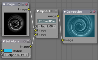
In the example above, notice how the blue tinge of the render input colors the swirl. You can use the Set Alpha node's color swatch with this kind of node map to add a consistent color to a BW image.
In the example map to the right, use the Alpha value of the SetAlpha node to give a desired degree of colorization. Thread the input image and the Set Alpha node into an AlphaOver node to colorize any black and white image in this manner. Note the ConvertPre-Multiply button is enabled, which tells the AlphaOver node not to multiply the alpha values of the two images together.
ID Mask Node
This node will use the Object Index pass (see RenderLayers) to produce an anti-aliased alpha mask for the object index specified. The mask is opaque where the object is, and transparent where the object isn't. If the object is partially transparent, the alpha mask matches the object's transparency. This post-process function fills in the jaggies with interpolated values.
Object Index
Object indices are only output from a RenderLayers node or stored in a multilayer OpenEXR format image.
|
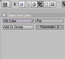
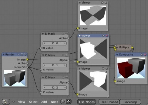
You can specify, for any of the objects in your scene, an Object Index as shown the right (the currently select object has an index of 2). When rendered, if Object Index passes are enabled, its index will be 2, and setting the ID Mask node to 2 will show where that object is in the scene.
This node is extremely well suited to removing the aliases shown as output from the Defocus node or DOF noodles caused by some objects being close to camera against objects far away.
Example
In this example, the left rear red cube is assigned PassIndex 1, and the right cube PassIndex 2. Where the two cubes intersect, there is going to be noticeable pixelation (jaggies) because they come together at a sharp angle and are different colors. Using the mask from object 1, which is smoothed (anti-aliased) at the edges, we use a Mix node set on Multiply to multiply the smoothed edges against the image, thus removing those nasty (Mick) Jaggies. Thus, being smoothed out, the Rolling Stones gather no moss. (I really hope you get that obscure reference :)
Note that the mask returns white where the object is fully visible to the camera(not behind anything else) and black for the part of the object that is partially or totally obscured by a fully or partially opaque object in front of it. If something else is in front of it, even if that thing is partially transparent and you can see the object in a render, the mask will not reflect that partially obscured part.
Math Node
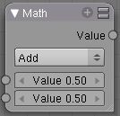
This node performs the selected math operation on an image or buffer. All common math functions are supported. If only an image is fed to one Value socket, the math function will apply the other Value consistently to every pixel in producing the output Value. Select the math function by clicking the up-down selector where the "Add" selection is shown.
The trig functions of Sine, Cosine, Tangent use only the top socket and accept values in radians between 0 and 2*pi for one complete cycle.
Known bug: the Top socket must get the image if the bottom socket is left as a value.
Examples
Manual Z-Mask
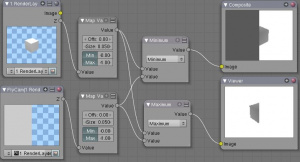
This example has one scene input by the top RenderLayer node, which has a cube that is about 10 BU from the camera. The bottom RenderLayer node inputs a scene (FlyCam) with a plane that covers the left half of the view and is 7 BU from the camera. Both are fed through their respective Map Value nodes to divide the Z buffer by 20 (multiply by .05, as shown in the Size field) and clamped to be a Min/Max of 0.0/1.0 respectively.
For the Minimum function, the node selects those Z values where the corresponding pixel is closer to the camera; so it chooses the Z values for the plane and part of the cube. The background has an infinite Z value, so it is clamped to 1.0 (shown as white). In the maximum example, the Z values of the cube are greater than the plane, so they are chosen for the left side, but the plane (FlyCam) Renderlayer's Z are infinite (mapped to 1.0) for the right side, so they are chosen.
Using Sine Function to Pulsate
This example has a Time node putting out a linear sequence from 0 to 1 over the course of 101 frames. The green vertical line in the curve widget shows that frame 25 is being put out, or a value of .25. That value is multiplied by 2*pi and converted to 1.0 by the Sine function, since we all know that Sine(2*pi/4)=Sine(pi/2)=+1.0.
Since the Sine function can put out values between -1.0 and 1.0, the Map Value node scales that to 0.0 to 1.0 by taking the input (-1 to 1), adding 1 (making 0 to 2), and multiplying the result by one half (thus scaling the output between 0 and 1). The default ColorRamp converts those values to a grayscale. Thus, medium gray corresponds to a 0.0 output by the sine, black to -1.0, and white to 1.0. As you can see, Sine(pi/2)=1.0. Like having your own visual color calculator! Animating this noodle provides a smooth cyclic sequence through the range of grays.
Use this function to vary, for example, the alpha channel of an image to produce a fading in/out effect. Alter the Z channel to move an scene in/out of focus. Alter a color channel value to make a color "pulse".
Brightening/Scaling a Channel
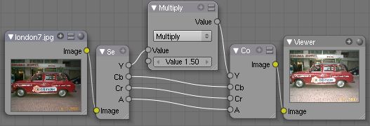
This example has a Multiply node increasing the luminance channel (Y) of the image to make it brighter. Note that you should use a Map Value node with Min() and Max() enabled to clamp the output to valid values. With this approach you could use a logarithmic function to make a high-dynamic range image. For this particular example, there is also a Brighten/Contrast node that might give simpler control over brightness.
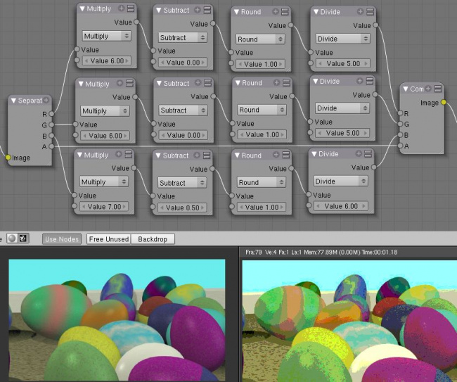
Quantize/Restrict Color Selection
In this example, we want to restrict the color output to only 256 possible values. Possible use of this is to see what the image will look like on an 8-bit cell phone display. To do this, we want to restrict the R, G and B values of any pixel to be one of a certain value, such that when they are combined, will not result in more than 256 possible values. The number of possible values of an output is the number of channel values multiplied by each other, or Q = R * G * B.
Since there are 3 channels and 256 values, we have some flexibility how to quantize each channel, since there are a lot of combinations of R*G*B that would equal 256. For example, if {R,G,B} = {4,4,16}, then 4 * 4 * 16 = 256. Also, {6,6,7} would give 252 possible values. The difference in appearance between {4,4,16} and {6,6,7} is that the first set (4,4,16} would have fewer shades of red and green, but lots of shades of blue. The set {6,6,7} would have a more even distribution of colors. To get better image quality with fewer color values, give more possible values to the predominant colors in the image.
Theory
To accomplish this quantization of an image to 256 possible values, lets use the set {6,6,7}. To split up a continuous range of values between 0 and 1 (the full Red spectrum) into 6 values, we need to construct an algorithm or function that takes any input value but only puts out 6 possible values, as illustrated by the image to the right. We want to include 0 as true black, with five other colors in between. The approach shown produces {0,.2,.4,.6,.8,1}. Dividing 1.0 by 5 equals .2, which tells us how far apart each quantified value is from the other.
So, to get good even shading, we want to take values that are 0.16 or less and map them to 0.0; values between 0.16 and 0.33 get fixed to 0.2; colorband values between 0.33 and 0.5 get quantized to 0.4, and so on up to values between 0.83 and 1.0 get mapped to 1.0.
Function f(x)
An algebraic function is made up of primitive mathematical operations (add, subtract, multiply, sine, cosine, etc) that operate on an input value to provide a desired output value.
|
The theory behind this function is scaled truncation. Let us suppose we want a math function that takes in a range of values between 0 and 1, such as .552, but only outputs a value of 0.0, 0.2, 0.4, etc. We can imagine then that we need to get that range 0 to 1 powered up to something 0 to 6 so that we can chop off and make it a whole number. So, with six divisions, how can we do that? The answer is we multiply the range by 6. The output of that first math multiply node is a range of values between 0 and 6. To get even divisions, because we are using the rounding function (see documentation above), we want any number plus or minus around a whole number will get rounded to that number. So, we subtract a half, which shifts everything over. The Round() function then makes that range 0 to 5. We then divide by 5 to get back a range of numbers between 0 and 1 which can then be combined back with the other color channels. Thus, you get the the function
f(x,n)=round[ x*n-1/2 ] /(n-1)
where n is the number of possible output values, and x is the input pixel color and f(x,n) is the output value. There's only one slight problem, and that is for the value exactly equal to 1, the formula result is 1.2, which is an invalid value. This is because the round function is actually a roundup function, and exactly 5.5 is rounded up to 6. So, by subtracting .501, we compensate and thus 5.499 is rounded to 5. At the other end of the spectrum, pure black, or 0, when .501 subtracted, rounds up to 0 since the Round() function does not return a negative number.
Sometimes using a spreadsheet can help you figure out how to put these nodes together to get the result that you want. Stepping you through the formula for n=6 and x=0.70, locate the line on the spreadsheet that has the 8-bit value 179 and R value 0.7. Multiplying by 6 gives 4.2. Subtracting 1/2 gives 3.7, which rounds up to 4. 4 divided by 5 = .8. Thus, f(0.7, 6) = 0.8 or an 8-bit value of 204. You can see that this same 8-bit value is output for a range of input values. Yeah! Geeks Rule! This is how you program Blender to do compositing based on Algebra. Thank a Teacher if you understand this.
Reality
To implement this function in Blender, consider the noodle above. First, feed the image to the Separate RGB node. For the Red channel, we string the math nodes into a function that takes each red color, multiplies (scales) it up by the desired number of divisions (6), offsets it by 0.5, rounds the value to the nearest whole number, and then divides the image pixel color by 5. So, the transformation is {0..1} becomes {0..6}, subtracting centers the medians to {-0.5...5.5} and the rounding to the nearest whole number produces {0,1,2,3,4,5} since the function rounds down, and then dividing by five results in six values {0.0,0.2,0.4,0.6,0.8,1.0}.
The result is that the output value can only be one of a certain set of values, stair-stepped because of the rounding function of the math node noodle. Copying this one channel to operate on Green and Blue gives the noodle below. To get the 6:6:7, we set the three multiply nodes to {6,6,7} and the divide nodes to {5,5,6}.
If you make this into a node group, you can easily re-use this setup from project to project. When you do, consider using a math node to drive the different values that you would have to otherwise set manually, just to error-proof your work.
Summary
Normally, an output render consists of 32- or 24-bit color depth, and each pixel can be one of millions of possible colors. This noodle example takes each of the Red, Green and Blue channels and normalizes them to one of a few values. When all three channels are combined back together, each color can only be one of 256 possible values.
While this example uses the Separate/Combine RGB to create distinct colors, other Separate/Combine nodes can be used as well. If using the YUV values, remember that U and V vary between -0.5 and +0.5, so you will have to first add on a half to bring the range between 0 and 1, and then after dividing, subtract a half to bring in back into standard range.
The JPG or PNG image format will store each of the colors according to their image standard for color depth (e.g. JPG is 24-bit), but the image will be very very small, since reducing color depth and quantizing colors is essentially what the JPEG compression algorithm accomplishes.
You do not have to reduce the color depth of each channel evenly. For example, if blue was the dominant color in an image, to preserve image quality, you could reduce Red to 2 values, Green to 4, and let the blue take on 256/(2*4) or 32 values. If using the HSV, you could reduce the Saturation and Value to 2 values (0 or 1.0) by Multiply by 2 and Divide by 2, and restrict the Hue to 64 possible values.
You can use this noodle to quantize any channel; alpha, speed (vector), z-values, and so forth.
Combine/Separate Nodes
All of these node do essentially the same thing: they split out an image into (or recombine an image from) its composite color channels. Each format supports the Alpha (transparency) channel. The standard way of representing color in an image is called a color space. There are several color spaces supported:
- RGB: Red-Green-Blue traditional primary colors, also broadcast directly to most computer monitors
- HSV: Three values, often considered as more intuitive than the RGB system (nearly only used on computers):
- Hue: the Hue of the color (in some way, choose a 'color' of the rainbow);
- Saturation: the quantity of hue in the color (from desaturate - shade of gray - to saturate - brighter colors);
- Value: the luminosity of the color (from 'no light' - black - to 'full light' - 'full' color, or white if Saturation is 0.0).
- YUV: Luminance-Chrominance standard used in broadcasting analog PAL (European) video.
- YCbCr: Luminance-ChannelBlue-ChannelRed Component video for digital broadcast use, whose standards have been updated for HDTV and commonly referred to as the HDMI format for component video.
See the global wikipedia for more information on color spaces.
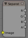
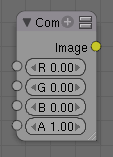
Separate/Combine RGBA Node
This node separates an image into its red, green, blue and alpha channels. There's a socket for each channel on the right.
This node combines separate input images as each color and alpha channel, producing a composite image. You use this node combine the channels after working on each color channel separately.
Examples
In this first example, we take the Alpha channel and blur it, and then combine it back with the colors. When placed in a scene, the edges of it will blend in, instead of having a hard edge. This is almost like anti-aliasing, but in a three-dimensional sense. Use this noodle when adding CG elements to live action to remove any hard edges. Animating this effect over a broader scale will make the object appear to "phase" in and out, as a "out-of-phase" time-traveling sync effect.
In this fun little noodle we make all the reds become green, and all the green both Red and Blue, and remove Blue from the image completely. Very cute. Very fun.
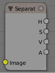
Separate/Combine HSVA Nodes
This node separates an image into image maps for the hue, saturation, value and alpha channels.
Use and manipulate the separated channels for different purposes; i.e. to achieve some compositing/color adjustment result. For example, you could expand the Value channel (by using the multiply node) to make all the colors brighter. You could make an image more relaxed by diminishing (via the divide or map value node) the Saturation channel. You could isolate a specific range of colors (by clipping the Hue channel via the Colorramp node) and change their color (by the Add/Subtract mix node).
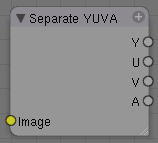
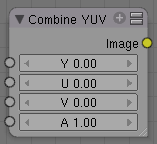
Separate/Combine YUVA Node
This node converts an RGBA image to YUVA color space, then splits each channel out to its own output so that they can be manipulated independently. Note that U and V values range from -0.5 to +0.5.
Combines the channels back into a composite image. If you do not connect any input socket, you can set a default value for the whole image for that channel using the numeric controls shown.
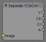
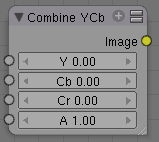
Separate/Combine YCbCrA Node
This node converts an RGBA image to YCbCrA color space, then splits each channel out to its own output so that they can be manipulated independently:
- Y: Luminance, 0=black, 1=white
- Cb: Chrominance Blue, 0=Blue, 1=Yellow
- Cr: Chrominance Red, 0=Red, 1=Yellow
Note: If running these channels through a ColorRamp to adjust value, use the Cardinal scale for accurate representation. Using the Exponential scale on the luminance channel gives high-contrast effect.
So, I kinda think you get the idea, and I was trying to think of some other creative way to write down the same thing, but I can't. So, you'll have to figure this node out on your own.
Alpha Convert
...
