「Doc:2.6/Manual/Materials/Nodes/Types/Input」の版間の差分
(→Geometry Node) |
(相違点なし)
|
2014年6月8日 (日) 12:59時点における版
Material Input Nodes
A starting material is created in the Materials Panel. The Nodes button is enabled to add that material to the list of noded materials shown in the Node Editor window header. Other inputs to the node map include:
- A value
- A color
- A texture
- Geometry
- Material
- Camera Data
- Lamp Data
Material Node
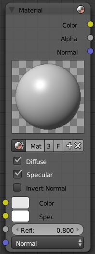
The Material node is used to add a material to the node program. Materials can be anything from pure shading to fully layered with textures. It inputs the main attributes of a material (color, alpha and normal vector) into the map.
Output
Materials can output color (which includes shading and any textures assigned to it), alpha, and the final normal calculated from any textures it has.
- Color - value of the color, combined by the node.
- Alpha - value of the alpha, combined by the node.
- Normal - direction of the normal, combined by the node.
Input
Materials can take inputs for colors, inputs for diffuse color and specularity color, a value for reflectivity, and a normal.
- Color - The base color of the paint. Can be set
- Spec - The color that is reflected as you get perpendicular to the light source reflecting off the surface. The color can be
- Refl: - The degree to which the material reflects light and gives off its color. The value can be provided by another node or set manually.
- Normal - The lighting condition.
Controls
- Material field
- You can browse and select materials here.
- Diffuse toggle
- Turn on/off Diffuse Color.
- Specular toggle
- Turns on/off Specularity calculation.
- Invert Normal toggle
- Inverts the material input normal when activated (which, of course, is a combination of the 3D normal given to it by the 3D object plus the normal input point).
Normal Override
The normal input socket does not in any way blend the source normal with the underlying geometry. Any plugged in Geometry here overrides the Normal lighting conditions.
|
Using the Material Node with Specularity
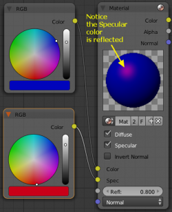
To make a material node actually generate a color, you have to specify at least a basic input color, and optionally a specularity color. The specularity color is the color that shines under intense light.
For example, consider the mini-map to the right. The base color, a dark blue, is connected from an RGB color generator node to the Color input socket. The specular color, yellow, is connected to the Spec input. Under Normal lighting conditions on a flat surface, this material will produce a deep blue color and, as you approach a spot perpendicular to the light, you will see the yellow specular color mix in.
Enable Spec
To see specularity, you have to enable it by clicking the blue Spec button located just below the material color swatch in the node.
|
Extended Material Node
Adds additional input and output channels to the material node.
Input
- Color
- Includes a color swatch, allowing you to select the color directly on the node.
- Mirror Color
- Color of mirrored reflection.
- Ambient
- Amount of global ambient color the material receives.
- Emit
- Amount of light to emit.
- SpecTra
- Alpha for the specular color.
- Ray Mirror
- Amount of reflectiveness of the object.
- Alpha
- Transparency of the material by setting all pixels in the alpha channel to the given value.
- Translucency
- Amount of diffuse shading on the back side
Output
Materials can additionaly output the followings:
- Diffuse - value of the diffuse color, combined by the node.
- Spec - value of the specular color, combined by the node.
- AO - value of the Ambient Occlusion, combined by the node.
Camera Data Node
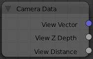
- View Vector
- A Camera space vector from the camera to the shading point.
- View Z Depth
- How far away each pixel is from the camera
- View Distance
- Distance from the camera to the shading point.
Lamp Data Node
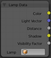
The Lamp Data node is used to obtain information related to a specified lamp object. Select a lamp object listed in the Lamp field, then the following outputs will be available:
- Color
- Lamp color multiplied by the lamp energy.
- Light Vector
- An unit vector in the direction from the shading point to the lamp.
- Distance
- Distance from the shading point to the lamp.
- Shadow
- Shadow color that the other objects cast on the shading point.
- Visibility Factor
- Light falloff ratio at the shading point.
The light textures and the shadow textures affect the Color and Shadow outputs, respectively.
Portability to Various Scenes
If multiple materials use a Lamp Data node linking to the same lamp object, including the Lamp Data node into a node group is recommended. Otherwise, when the mesh objects are imported to the other scene, all the materials may need to be modified.
|
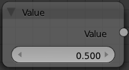
Value Node
The Value node has no inputs; it just outputs a numerical value (floating point spanning 0.00 to 1.00) currently entered in the NumButton displayed in its controls selection.
Use this node to supply a constant, fixed value to other nodes' value or factor input sockets.
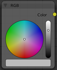
RGB Node
The RGB node has no inputs. It just outputs the value Color currently selected in its controls section.
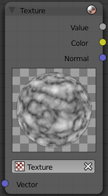
Material Node "Texture"
A texture, from the list of textures available in the current blend file, is selected and introduced through the value and/or color socket.
Input
- Vector
- Uses for map the texture to a specific geometric space.
Outputs
- Value
- Straight black-and-white value of the texture, combined by the node.
- Color
- Texture color output, combined by the node.
- Normal
- Direction of normal texture, combined by the node.
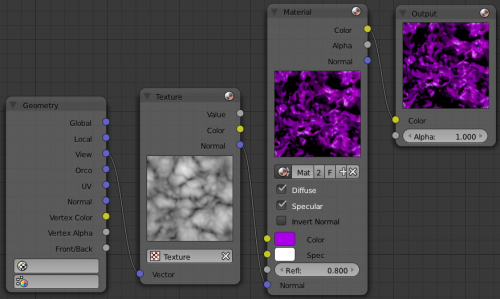
In the example to the right, a cloud texture, as it would appear to a viewer, is added to a base purple material, giving a velvet effect.
Note that you can have multiple texture input nodes. With nodes, you simply add the textures to the map and plug them into the map.
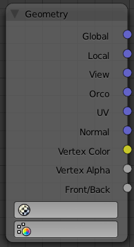
Geometry Node
The geometry node is used to specify how light reflects off the surface. This node is used to change a material's Normal response to lighting conditions.
Use this node to feed the Normal vector input on the Material node, to see how the material will look (i.e. shine, or reflect light) under different lighting conditions. Your choices are:
- Global
- Global position of the surface.
- Local
- Local position of the surface.
- View
- Viewed position of the surface.
- Orco
- Using the Original Coordinates of the mesh.
- UV
- Using the UV coordinates of the mesh, selected in the field in bottom node.
- Normal
- Surface Normal; On a flat plane with one light above and to the right reflecting off the surface.
- Vertex Color
- Allows for output value of group vertex colors, selected in the field in bottom node.
- Vertex Alpha
- Allows for output alpha value of vertex.
- Front/Back
- Allows for output to take into account front or back of surface is light relative the camera.
Note
These are exactly the same settings as in the Mapping panel for Textures, though a few settings - like Stress or Tangent - are missing here. Normally you would use this node as input for a Texture Node.
|
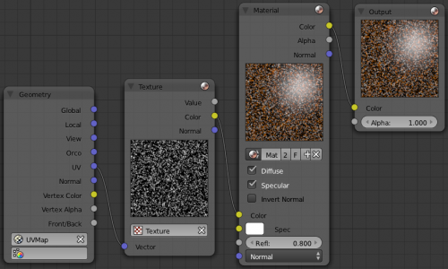
Geometry Node Example using a UV image
E.g.: To render an UV-mapped image, you would use the UV output and plug it into the Vector Input of a texture node. Then you plug the color output of the texture node into the color input of the material node - which corresponds to the setting on the Map To panel.
