Doc:2.6/Manual/Rigging/Armatures/Bones
Bones
Bones are the base elements of armatures.
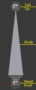
They have three elements:
- the “start point” named root or head,
- the “body” itself,
- and the “end point” named tip or tail.
Select the default armature and press ⇆ Tab to enter Edit mode. As you can see, in this mode you can select the root and the tip, and move them as you do with mesh vertices (don't lose too much time here though, specific pages about selecting and editing will come later).
Both root and tip (the “ends”) define the bone by their respective position.
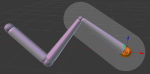
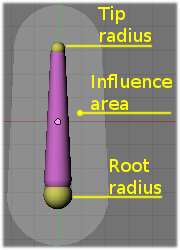
They also have a radius property, only useful for the envelope deformation method (see below).
Bones Visualization
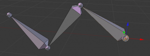
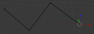
Bones can be visualized in various ways: Octahedron, Stick, B-Bone, Envelope and Wire. Custom shapes can be used, too!
Since armatures are made of bones, you’ll find more about this when we’ll talk about Armatures Visualization.
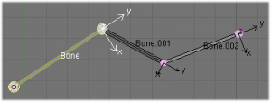
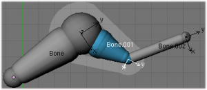
Activating Axes checkmark on the Armature/Display panel, will show local axes for each bone's tip. The Y axis is always aligned along the bone, oriented from root to tip. So, this is the "roll" axis of the bones.
Bones properties
When bones are selected (hence in Edit mode and Pose mode), their properties are shown in the Bone button context of the Properties window.
This shows different panels used to control features of each selected bone; the panels change depending on which mode you’re working in.
Bones Rigidity
Even though bones are rigid (i.e. behave as rigid sticks), they are made out of segments. Segments are small, rigid linked elements that can rotate between each other. By default, each new bone has only one segment and as such it cannot “bend” along its length. It is a rigid bone.
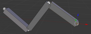
You can see these segments in Object mode and in Pose mode, and only if bones are visualized as B-bones; while in Edit mode bones are always drawn as rigid sticks. Note that in the special case of a single bone, you can't see these segments in Object mode, because they're aligned.
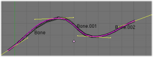
When you connect bones to form a chain, Blender calculates a Bezier curve passing through all the bones' ends, and bones' segments in the chain will bend and roll to follow this invisible curve.
You have no direct access to this curve; you can only control it to some extent using bone properties, as explained in the editing pages.
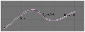
In An armature of B-Bones in Edit mode we connected 3 bones, each one made of 5 segments. These are B-bones but as you see, in Edit mode they are shown as rigid elements. Look at The same armature in Object mode: now, in Object mode, we can see how the bones' segments smoothly “blend” into each other, even for roll.
Of course, a geometry influenced by the chain is smoothly deformed according to the Bezier curve! In fact, smooth bones are an easy way to replace long chains of many small rigid bones posed using IK...
However, if the chain has an influence on objects rather than geometry, the segments' orientation is not taken in account (details are explained in the skinning part).
When not visualized as B-Bones, bones are always shown as rigid sticks, even though the bone segments are still present and effective (see skinning to ObData).
This means that even in e.g. Octahedron visualization, if some bones in a chain have several segments, they will nonetheless smoothly deform their geometry...
Bones influence
Basically, a bone controls a geometry when vertices "follow" the bone. This is like how the muscles and skin of your finger follow your finger-bone when you move a finger.
To do this, you have to define how much a bone influences a certain vertex.
The simplest way is to have each bone affecting those parts of the geometry that are within a given range from it. This is called the envelope technique, because each bone can control only the geometry “enveloped” by its own influence area.
If a bone is visualized as Envelope, in Edit mode and in Pose mode you can see the area of influence, which depends on:
- the distance property
- the root's radius and the tip's radius.
All these influence parameters are further detailed in the skinning pages.
