Extensions:2.6/Py/Scripts/Neuro tool/Measurement
| UI location | View3D » Measurement Tools | ||
|---|---|---|---|
| Version | 1.2.2 | Author(s) | Anne Jorstad, Biagio Nigro |
| Blender | 2.68-2.76 | License | GPL |
| File name | NeuroMorph_Measurement_Tools.py |
|---|---|
| Current version download | https://github.com/ajorstad/NeuroMorph |
OVERVIEW
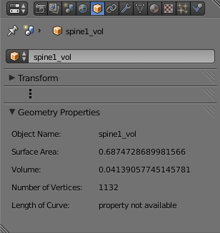
This module measures surface areas, volumes, and lengths of regions of meshes specified by a user-defined selection of vertices. New objects are created as children of the original mesh object, and the measurements are stored in appropriate property variables of these children objects in the Geometry Properties panel of the Object context (bottom right of the Blender interface, see below for details). Objects are named, optionally, according to a naming convention developed for neural structures. Measurements can be exported into a .txt file that can be read by Excel.
DESCRIPTION
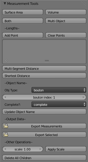
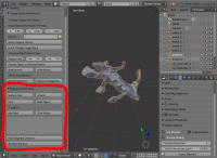
The script inserts a panel called "Measurement Tools" into the tool region at the left of the Blender interface. Each measurement operation creates a new object as a child of the original object. Objects are named, optionally, using the naming convention described below.
Making Surface Area and Volume Measurements
1. Select the mesh object to be measured and enter Edit Mode by clicking tab on the keyboard.
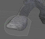
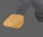
2. Select the vertices of the subregion to be measured. This can be done using the lasso select (shortcut: CtrlLMB ![]() ) to drag the mouse to form a freehand selection area. Non-visible vertices can be selected by disabling the "Limit selection to visible" option (
) to drag the mouse to form a freehand selection area. Non-visible vertices can be selected by disabling the "Limit selection to visible" option (![]() at the bottom of the Blender interface in Edit Mode). Vertices can be deselected by hitting the A key.
at the bottom of the Blender interface in Edit Mode). Vertices can be deselected by hitting the A key.
|
|
3. Click on either the 'Surface Area' button, or the 'Volume' button in the 'Measurement tools' panel. Make sure to give a name to the feature measured, eg. spine1.
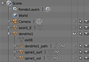
- Surface Area: Measures the surface area of the continuous region defined by the currently selected vertices. Creates a new mesh object as a child of the active object called name_surf that consists of exactly those vertices selected.
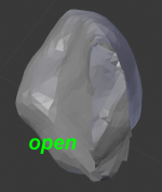
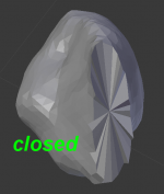
- Volume: Measures the volume of the continuous regions defined by the current selected vertices. Creates a new mesh object as a child of the active object called name_vol that consists of the selected vertices, and in addition, any additional vertices that are required to close any open holes of the selected region, as volume can only be defined on a closed mesh. Provides both volume and surface area measurements, where the surface area includes the areas of the triangles required to close any open holes, so may be larger than the surface area found from the "Surface Area" button.
|
|
- Both: Calls both Surface Area and Volume.
- Multi Object: Measures both surface area and volume of all selected objects. This button is useful for measuring many small closed objects at once, and only the name_vol objects (which contain both surface area and volume measurements) are created.
4. The measured feature will be a child of the original object, and will be hidden (to make visible, click on the eye icon). It will be listed in the "Outliner" window on the right.
5. The measured values are displayed in the "Geometry Properties" panel of the "Object" context (![]() ) in the Properties window (bottom right of the Blender interface).
) in the Properties window (bottom right of the Blender interface).
Length Measurements
Select the mesh object to be measured and enter Edit Mode. Points are added to the point list (the index of each currently added point is displayed), and then the length of the curve connecting the points can be calculated. Two different length calculations are provided.
- Add Point: Adds the selected vertex to point list.
- Clear Points: Clears the point list.
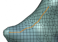
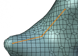
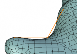
- Multi-Segment Distance: Measures the length of the path that connects all points in the point list with linear segments. Creates a new curve object as a child of the active object called name_MS_dist that consists of the points in the point list and the linear segments connecting them. (The precision of this measurement, compared to the length of the curve that lies exactly along the surface of the selected mesh profile, depends entirely on the user input sampling.)
|
|
- Shortest Distance: Measures the shortest distance between exactly two selected vertices along a path that connects consecutive vertices on the surface of the mesh. Creates a new curve object as a child of the active object called name_2pt_dist that consists of a piecewise linear path whose segments connect the mesh vertices that determine the shortest path through the mesh surface.
Naming Convention
The naming convention allows the user to define new object names either freely or following a naming scheme that depends on the object type and numerical index. All names will be appended as described above, depending on the measurement being performed. The provided options are:
- "other": gives the user the option to assign a custom name to the mesh by entering it in the box provided.
- "Axon": has a numerical index and a type (excitatory, inhibitory, unknown, N/A).
- "Dendrite": has a numerical index.
- "Spine": has a numerical index.
- "Bouton": has a numerical index.
- "Synapse": depends on the identity of the dendrite and the axon it connects, and also the identity of the dendritic spine and axonal bouton. For example, the name of an inhibitory synapse connecting spine 4 of dendrite 14 and bouton 2 of axon 23 will be syn_d14s4a23b2_I.
- Update Object Name: Changes name of currently selected object to abide by the naming convention.
Output Data
- Export Measurements: Exports all scene measurements to the user-defined file by listing all object information with column format "Object Name,Parent,Surface Area,Volume,Number of Vertices,Length,Path" into a .txt file that can be read by Excel.
- Export Selected: Exports the measurements of only the selected objects and their children.
Other Options
- Apply Scale: Rescales all objects and child objects by the scale factor defined by "scale".
- Delete All Children: Deletes all children of the selected objects, regardless of their type.
