Doc:2.6/Manual/Composite Nodes/Types/Distort
Page status (reviewing guidelines)
Copy
This page is a copy of the same page in 2.4 manual, need to be updated
|
Composite Distort Nodes
These nodes distort the image in some fashion, operating either uniformly on the image, or by using a mask to vary the effect over the image.
Translate Node
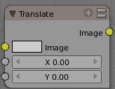
The translate node translates (moves) an image by the specified amounts in the X and Y directions. X and Y are in pixels, and can be positive or negative. To shift an image up and to the left, for example, you would specify a negative X offset and a positive Y.
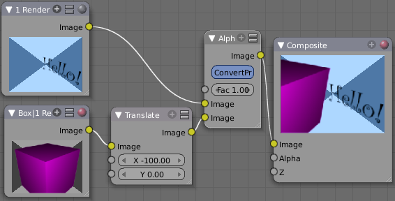
Use this node to position an image into the final composite image. Usually, the output of this node is routed to an AlphaOver or Mix node to mix it with a base image. In the example below, the RenderLayer input from one scene (box) is translated over to the left (a negative X translation) and alphaovered with a Hello scene RenderLayer input
Example: Using the Translate Node to Roll Credits
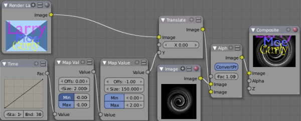
At the end of your fantastic animation, you'll want to give credit where credit is due. This is called rolling the credits and you see the names of everyone involved scroll up over a background image or sequence. The mini-map below shows an example of how to roll credits using the Translate node.
In this node map, the RenderLayer input has a list of the people involved and is 150 pixels high; it is the image input into the Translate Node. The Y value (vertical) offset of the Translate node comes from a scaled time factor that varies from -150 to 150 over 30 frames. The Translated image is overlaid on top of a background swirl image. So, over the course of 30 frames, the Translate node shifts the image from down by 150 pixels (off the bottom of the screen), up through and overlaid on top of the swirl, and finally off the screen to the top. These frames are generated when the Render Animation buttons are set and Anim is pressed. Right now, frame 21 is showing Moe and Curly, and Larry has scrolled off the screen.
Alpha channel
Be sure to save your credits image in a format that supports an alpha channel, such as PNG, so that the AlphaOver node can overlay it on the background and let the background show through.
|
You could have parented and animated all of the text to roll up past your camera, but rendering would have taken forever. Using the translate node is much faster to composite, and more flexible. To add someone to the list, simply change the credits image and re-animate. Since it is simple image manipulation, Blender is blazingly fast at regenerating your credits. Similarly, changing the background is rock simple as well; simply load up a different background image and re-Animate.
Example: Moving a Matte
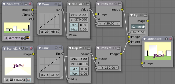
In some 2D and 3D animations and movies, a matte painting is used as the background. In most scenes it is still, however you can easily move it using the Translate node. Mattes are huge; the example used below is actually 1440x600 pixels, even though the scene being rendered is for TV. This oversizing gives us room to move the matte around. The example noodle below introduces a dancing "Hello!" from stage right in frames 1-30. As the "Hello" reaches center stage, we fake a camera move by moving the matte to the left, which makes it look like the "Hello!" is still moving as the camera moves with it.
Use the Map Value node to scale the X (left to right) offsets that feed the Translate node. Note that offsets are used to position the dancing "Hello!" down to look like it is walking along the street (in the render scene, it is centered on camera and just dances in place). The matte is adjusted up to fake a camera height of an observer, bringing the horizon up.
Example: Shake, Rattle and Roll
A real world effect is the shaking of the camera. BOOM! We expect to feel the impact and see it rock our world. In our virtual CG world, though, we are in the vaccuum of space. So, we have to fake a camera being shook. There are two points in the development cycle to do this: at Render-Scene time, and at Composite time.
At Render-Scene time, the modeler would introduce an Ipo curve and keyframes that rotate and/or move the camera for a short amount of time. The advantage to render-scene shake is that the artist handles it and the editor does not have to worry about it; one less thing to do thank goodness. The disadvantage is that the artist may only be modeling the actors, and not the background scenery, props, or matte, so any shake they introduce does not transfer to the set, props, or backdrop. Therefore, it is best to introduce camera shake after all scenes have been rendered and assembled and when they are being composited.
There are two aspects to being bumped, or tripping over the tripod, or having an explosion go off next to you, or an airplane have a near miss as it flies by, or throwing up on a long sea voyage, or surviving an earthquake: camera motion and image blur (I know you were thinking expletives and changing your underpants, but this is about compositing).
Camera Motion happens because the camera physically gets moved; but its mass and its tripod also acts as a dampening device, softening out and absorbing the initial bump. The cameraman also acts as a dampener, and also as a corrector, trying to get the camera back to where it was pointed originally.
There can be quite a delay between the shock and the correction; for example, a lone actor/cameraman may trip on the tripod coming out from behind the camera, come into frame, realize the camera is off, and then come back to correct it. It all depends on the artistic effect and story you want to convey.
The image blur comes into play because the shake happens so rapidly that the image is blurred in the direction of the shake. However, the blur is more when the camera is being pushed back into position, and less when the camera is at the extreme of its deflection, since it is decelerating at the apex of its movement. Like motion, blur is the most during the initial shock, and less as things slow down and get under control. Also, the camera may go out of focus and come back into focus at the end of the shake.
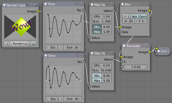
To use Blender nodes to mimic Camera Motion, use the noodle shown below. The noodle has a Blur group on top that feeds a Translate group below it.
In the above example, we use a Time curve that mimics the intensity and duration of a typical BOOM!. In this case, both curves have four peaks within a 16-frame period to mimic a BOOM! (in fact one curve was constructed and then duplicated to make the other, to ensure that the bulk of both curves was exactly the same). Notice how the curve dampens (decreases in magnitude as time progresses) as discussed above. Notice how the curve slows down (increasing period) to mimic the cameraman getting it back under control. Notice that the curve is sinusoidal to mimic over-correction and vibration.
BOOM! to the Left: The translate curve starts at 0.5. Maximum deflection up is fully a half, yet down is only a quarter. This offset mimics a BOOM! off to our left, since the camera shakes more to the right, away from the BOOM!
Motion and Blur are the same but different: Notice that the two curves are identical except for the highlighted start and end dots; we want zero blur and zero offsets before and after the shake, but minimum blur when there is maximum translate. The two Map Value node settings are different to achieve this; the math is left to the reader.
Use this Blender noodle to mimic camera shake. The amount of shake is set by the Size values, and the blur should be proportional to the amount and direction of motion (predominantly X in this example). Use the Time start and end to vary the duration of the shake; ten seconds for an earthquake, one minute for a ship rolling in the seas, a half second as an F-14 flies by and takes your ear off. Author's note: I noticed cool camera shakes while watching the Halo 3 previews.
Rotate Node
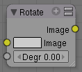
This node rotates an image. Positive values rotate clockwise and negative ones counterclockwise.
Scale Node
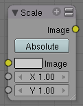
This node scales the size of an image. Scaling can be either absolute or relative. If Absolute toggle is on, you can define the size of an image by using real pixel values. In relative mode percents are used.
For instance X: 0.50 and Y: 0.50 would produce image which width and height would be half of what they used to be. When expanding an image greatly, you might want to blur it somewhat to remove the square corners that might result. Unless of course you want that effect; in which case, ignore what I just said.
Use this node to match image sizes. Most nodes produce an image that is the same size as the image input into their top image socket. So, if you want to uniformly combine two images of different size, you must scale the second to match the resolution of the first.
Flip Node
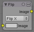
This node flips an image at defined axis that can be either X or Y. Also flipping can be done on both X and Y axis' simultaneously.
You can use this node to just flip or use it as a part of mirror setting. Mix half of the image to be mirrored with its flipped version to produce mirrored image.
Displace Node
Ever look down the road on a hot summer day? See how the image is distorted by the hot air? That's because the light is being bent by the air; the air itself is acting like a lens. This fancy little node does the same thing; it moves an input image's pixels based on an input vector mask (the vector mask mimics the effect of the hot air).
This can be useful for a lot of things, like hot air distortion, quick-and-dirty refraction, compositing live footage behind refracting objects like looking through bent glass or glass blocks, and more! Remember what HAL saw in 2001:Space Odyssey; that distorted wide-angle lens? Yup, this node can take a flat image and apply a mask to produce that image.
The amount of displacement in the X and Y directions is determined by
- The value of the mask's channels:
- The scaling of the mask's channels
The (red) channel 1's value determines displacement along the positive or negative X axis. The (green) channel 2's value determines displacement along the positive or negative Y axis.
If both the channels' values are equal (i.e. a greyscale image), the input image will be displaced equally in both X and Y directions, and also according to the X scale and Y scale buttons. These scale button act as multipliers to increase or decrease the strength of the displacement along their respective axes. They need to be set to non-zero values for the node to have any effect.
Because of this, you can use the displace node in two ways, with a greyscale mask (easy to paint, or take from a procedural texture), or with a vector channel or RGB image, such as a normal pass, which will displace the pixels based on the normal direction.
Example
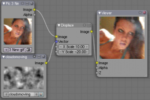
In this example, she's singing about dreams of the future. So, to represent this, we use a moving clouds texture (shot just by rendering the cloud texture on a moving plane) as the displacement map. Now, the colors in a black and white image go from zero (black) to one (white), which, if fed directly without scaling would only shift the pixels one position. So, we scale their effect in the X and Y direction.
Upon reviewing it, sometimes stretching in both the X and Y direction made her face look fat, and we all can guess her reaction to looking fat on camera. SO, we scale it only half as much in the X so her face looks longer and thinner. Now, a single image does not do justice to the animation effect as the cloud moves, and this simple noodle does not reflect using blur and overlays to enhance (and complicate) the effect, but this is the core.
Photos courtesy of Becca, no rights reserved. See also some movies of this node in action, made by the wizard programmer himself, by following this external link
Map UV Node
So, I think we all agree that the problem is...we just don't know what we want. The same is true for directors. Despite our best job texturing our models, in post production, inevitably the director changes their mind. "Man, I really wish he looked more ragged. Who did makeup, anyway?" comes the remark. While you can do quite a bit of coloring in post production, there are limits. Well, now this little node comes along and you have the power to re-texture your objects after they have been rendered. Yes, you read that right; it's not a typo and I'm not crazy. At least, not today.
Using this node (and having saved the UV map in a multilayer OpenEXR format image sequence), you can apply new flat image textures to all objects (or individual objects if you used the very cool ID Mask Node to enumerate your objects) in the scene.
Thread the new UV Texture to the Image socket, and the UV Map from the rendered scene to the UV input socket. The resulting image is the input image texture distorted to match the UV coordinates. That image can then be overlay mixed with the original image to paint the texture on top of the original. Adjust alpha and the mix factor to control how much the new texture overlays the old.
Of course, when painting the new texture, it helps to have the UV maps for the original objects in the scene, so keep those UV texture outlines around even after all shooting is done.
Examples
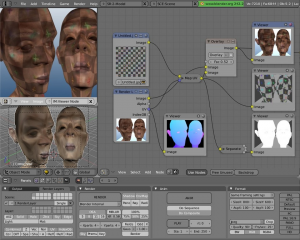
In the example to the right, we have overlaid a grid pattern on top of the two Emo heads after they have been rendered. During rendering, we enabled the UV layer in the RenderLayer tab (Buttons window, Render Context, RenderLayer tab). Using a mix node, we mix that new UV Texture over the original face. We can use this grid texture to help in any motion tracking that we need to do.
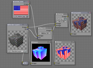
In this example, we overlay a flag on top of a cubie-type thing, and we ensure that we Enable the Alpha pre-multiply button on the Mix node. The flag is used as additional UV Texture on top of the grid. Other examples include the possibility that we used an unauthorized product box during our initial animation, and we need to substitute in a different product sponsor after rendering.
Of course, this node does NOT give directors the power to rush pre-production rendering under the guise of "we'll fix it later", so maybe you don't want to tell them about this node. Let's keep it to ourselves for now.
Crop Node
The Crop Node takes an input image and crops it to a selected region.
- Crop Image Size
- When enabled, the image size is cropped to the specified region. When disabled, image remains the same size, and uncropped areas become transparent pixels.
- Relative
- When enabled, crop dimensions are a percentage of the image's width and height. When disabled, the range of the sliders are the width and height of the image in pixels.
- Crop Region Values
- These sliders define the lower, upper, left, and right borders if the crop region.
Lens Distortion
Use this node to simulate distortions that real camera lenses produce.
- Distort
- This creates a bulging or pinching effect from the center of the image.
- Dispersion
- This simulates chromatic aberration, where different wavelengths of light refract slightly differently, creating a rainbow colored fringe.
- Projector
- Enable or disable slider projection mode. When on, distortion is only applied horizontally. Disables Jitter and Fit.
- Jitter
- Adds jitter to the distortion. Faster, but noisier.
- Fit
- Scales image so black areas are not visible. Only works for positive distortion.
