利用者:Rking/Doc:2.6/Manual/Modifiers/Generate/Subsurf
Subdivision Surfaces ("Subsurf") Modifier
Mode: Any Mode
Panel: Modifiers > Add > Generate > Subdivision Surface
Hotkey: Using the regular #s, not keypad #s: Ctrl0, Ctrl1, Ctrl2, Ctrl3, Ctrl4, Ctrl5. Note, this only affects the View value while leaving Render at 2 (see below).
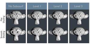
Subdivision Surface (Subsurf in short) is a method of subdividing the faces of a mesh to give a smooth appearance, to enable modeling of complex smooth surfaces with simple, low-vertex meshes. This allows high resolution mesh modeling without the need to save and maintain huge amounts of data and gives a smooth organic look to the object.
This process creates virtual geometry that is generated at display time, but it can be converted to real geometry that you could edit with the Apply feature. Like the rest of the modifiers, this is a non-destructive tool, not affecting the underlying mesh until you hit Apply (and even then, you have Undo/Redo capabilities).
Also, like the rest of the Modifiers, order of execution has an important bearing on the results. For this, see the Order of the Modifier Stack section on this page.
There are two algorithms available: Simple (subdivides mesh) and the default Catmull-Clark (subdivides and smooths mesh).
Keep in mind that this is a different operation than its companion, Smooth Shading. You can see the difference between the two in the grid image to the right.
Subsurf's Bigger Brother: MultiResolution
Before you go too far with Subsurfing, it is important to also know about another way to subdivide: the MultiResolution Modifier. This differs from Subsurfing in that MultiRes allows you to edit the mesh at several subdivision levels without losing information at the other levels. It is slightly more complicated to use, but more powerful.
Options
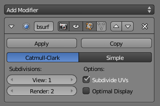
Subsurf is a modifier. To add it to a mesh, press Add Modifier and select Subdivision Surface from the list.
- Type
- This toggle button allows you to choose the subdivision algorithm:
- Catmull-Clark - The default option, subdivides and smooths the surfaces. According to its Wikipedia page, the "arbitrary-looking formula was chosen by Catmull and Clark based on the aesthetic appearance of the resulting surfaces rather than on a mathematical derivation."
- Simple – Only subdivides the surfaces, without any smoothing (similar to W → Subdivide, in Edit mode). Can be used, for example, to increase base mesh resolution when using displacement maps or textured emitters with indirect lighting.
- Subdivisions - Recursively adds more geometry. For some detailed examples of the numbers, see the Performance Considerations section.
-
- View - Affects the display resolution for the 3D views only.
- Render - Affects the subdivision level used during rendering. For the internal Blender Render, the status line at the top of the Render Result will tell you the current Frame, then after that the number of the final, generated vertices and faces. This can give you a clue at the overall performance impact of all Modifiers.
The right combination of these settings will allow you to keep a fast and lightweight approximation of your model when interacting with it in 3D, but use a higher quality version when rendering.
| View less than or equal to Render | |
| Be careful not to set the View higher than the Render setting, or else your preview would display higher quality than your render. |
- Options
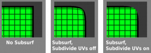
- Subdivide UVs: When enabled, the UV maps will also be subsurfed (i.e. Blender will add “virtual” coordinates for all sub-faces created by this modifier). The easiest way to understand its effects is to view Manual-Modifiers-Generate-Subsurf-SubdivideUVsExample.blend.
- Optimal Display: Restricts the wireframe display to only show a warped mesh cage edges, rather than the subdivided result, to help visualization. Without this, Edit Mode can look cluttered with lines that are not really there.
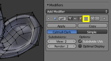
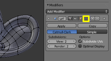
To view and edit the results of the subdivision (“isolines”) while you’re editing the mesh, you must enable the Editing Cage mode by clicking in the inverted triangle button in the modifier panel header (next to the arrows for moving the modifier up and down the stack). This lets you grab the points as they lie in their new subdivided locations, rather than on the original mesh.
Notice the comparison of screenshots to the right. With the edit cage off, some vertices are buried under the subsurfed mesh. With dense vertex configurations, you might have to even click the "Eye" icon so that you can see these vertices. The "edit cage on" version does not suffer from this problem. It does, however, have its own disadvantage---it can look too nice. Notice the three quads running in the middle of Suzanne's ear. You can only tell how crooked they are in the "edit cage off" version. When you are modelling, you will more often want to see your mesh deformities in their full ugliness---so you can apply your skills until it is sheer prettiness.
Order of the Modifier Stack
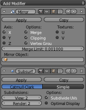
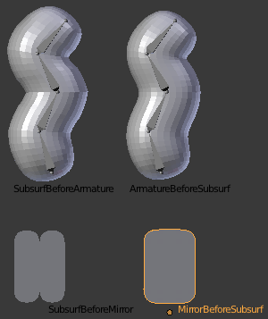
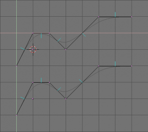
The evaluation order of Modifiers is often significant, but especially so in the case of the Subsurf. The key to deciding your Modifier stack order is to picture the changes at each step, perhaps by temporarily Apply'ing the Modifiers, or perhaps by simply tinkering with the order until things come out right. To see the file behind these screenshots, you can look at Manual-Modifiers-Generate-Subsurf_OrderOfExecution.blend.
Control
Subsurf rounds off edges, and often this is not what you want. There are several solutions.
Weighted Creases
Mode: Edit Mode (Mesh)
Panel: 3D View → Transform Properties
Hotkey: ⇧ ShiftE
Menu: Mesh → Edges → Crease Subsurf
Weighted edge creases for subdivision surfaces allows you to change the way Subsurf subdivides the geometry to give the edges a smooth or sharp appearance.
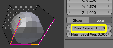
The crease weight of selected edges can be changed using Transform Properties (N) and change the Median Transform slider. A higher value makes the edge “stronger” and more resistant to subsurf. Another way to remember it is that the weight refers to the edge’s sharpness. Edges with a higher weight will be deformed less by subsurf. Recall that the subsurfed shape is a product of all intersecting edges, so to make the edges of an area sharper, you have to increase the weight of all the surrounding edges.
Edge Loops
Mode: Edit Mode (Mesh)
Hotkey: CtrlR
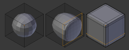
The Subsurf modifier demonstrates why good, clean topology is so important. As you can see in the figure, the Subsurf modifier has a drastic effect on a default Cube. Until you add in additional Loops (with CtrlR), the shape is almost unrecognizable. A mesh with a deliberate topology has good placement of Edge Loops, which allow the placement of more Loops (or removal of Loops, with X » Edge Loop) to control the sharpness/smoothness of the resultant mesh.
Combination
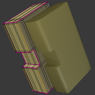
It is valuable to know the use of all three tools: Smooth/Flat Shading, Edge Creases and Edge Loops. Consider the task of modelling a 2"x4" block of wood that has had a notch cut out. The factory edges are rounded off (a good task for Smooth Shading and some Edge Loops), but the edges where the saw touched are a crisp (a good task for Flat Shading and Edge Crease). Note that we had to add some extra edge loops near the Creased edges -- this was only to limit the effects of the Smooth Shading, which bleeds over onto the flat faces.
Limitations & Workarounds
Blender’s subdivision system produces nice smooth subsurfed meshes, but any subsurfed face (that is, any small face created by the algorithm from a single face of the original mesh), shares the overall normal orientation of that original face.
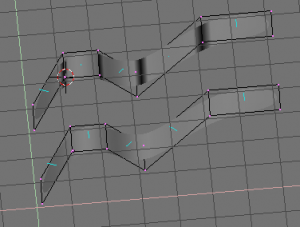
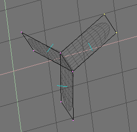
Abrupt normal changes can produce ugly black gouges (See: Solid view of subsurfed meshes with inconsistent normals (top) and consistent normals (bottom)), even though these flipped normals are not an issue for the shape itself, as (See: Side view of subsurfed meshes).
A quick way to fix this (one which works 90% of the time) is to use Blender's "Make Normals Consistent" operation: In Edit Mode, select all with A, then hit CtrlN to recalculate the normals to point outside. If you still have some ugly black gouges after a CtrlN, you will have to manually flip some normals. To do this (still in Edit Mode), Look in the N Properties Panel, on the right, in the Mesh Display subsection (it is roughly the 3rd up from the bottom). There you can turn on the little cyan "Face Normals" sticks (as seen in our pictures to the right), and you can change their size to be more appropriate for the scale of your mesh. If you then go around your mesh in Face Select mode (Ctrl⇆ Tab,F) selecting bad faces, you can then use the Specials » Flip Normals functionality (shortcut: W,N) to fix them. Smoothing out normals is good for the mesh, and it's good for the soul.
Note that one problem that will prevent Blender from automatically recalculate normals correctly is if the mesh is not “Manifold”. A “Non-Manifold” mesh contains an edge that is not connected to (exactly) two faces. Generally, this means that “out” cannot be computed.
(A “Non-Manifold” mesh) shows a very simple example of a “Non-Manifold” mesh. In general a non-manifold mesh occurs when you have internal faces or edges that are unexpectedly open.
A non-manifold mesh is not a problem for conventional meshes, but can give rise to ugly artifacts when subsurfed. Also, it does not allow decimation, so it is better to avoid them as much as possible.
To locate the non-Manifold components, you can be in either Vertex Select mode or Edge Select mode and deselect all vertices. Now, either go to Select » Non Manifold or hit CtrlAlt⇧ ShiftM. Sometimes, it can take some clever work to make these areas Manifold, but with determination and creativity you will be able to figure it out. Sometimes it is only a matter of Removing Doubles (W,R) or of manually merging some vertices (AltM).
Performance Considerations
Great levels of Subsurf demands more video memory, and a faster graphics card. Blender could potentially crash if your level of Subsurf surpasses your system memory.
Note about potential crashes: Be aware that the Subsurf Modifier will need more and more memory at higher levels of subsurf, and, the more dense your base mesh, the more memory you will need. In 32 bit systems, Blender could potentially crash with malloc errors, when you surpass 2~3 GiB of memo ry used. This is not a Blender bug. Blender, when paired with a 64 Bit System, could use 64 GiB of memory, thus reducing the chances of malloc() errors.
Another note about using a high levels of Subsurf with a graphics card with low total amount of Vram. When you move, edit, or otherwise work in your mesh, some parts of the geometry will disappear visually. Your mesh will actually be O.K., because the render is generated using your Object Data, even though it cannot be shown by your graphics card.
The resulting Vertex, Edge, and Face counts from the Modifier's effect on a Cube, Quadrilateral Plane, and Triangle can be found in these tables:
| Cube Subdivision Level | Resulting Verts | Resulting Edges | Resulting Faces |
|---|---|---|---|
| 0 | 8 | 12 | 6 |
| 1 | 26 | 48 | 24 |
| 2 | 98 | 192 | 96 |
| 3 | 386 | 768 | 384 |
| 4 | 1538 | 3072 | 1536 |
| 5 | 6146 | 12288 | 6144 |
| 6 | 24578 | 49152 | 24576 |
| Formulae | 3*2**(2*n)+4)/2 | 3*4**n | verts - 2 |
While we're at it, here is the pattern for subdividing a quadrilateral plane:
| Quad Subdivision Level | Resulting Verts | Resulting Edges | Resulting Faces |
|---|---|---|---|
| 0 | 4 | 4 | 1 |
| 1 | 9 | 12 | 4 |
| 2 | 25 | 40 | 16 |
| 3 | 81 | 144 | 64 |
| 4 | 289 | 544 | 256 |
| 5 | 1089 | 2112 | 1024 |
| 6 | 4225 | 8320 | 4096 |
| Formulae | ((2**n+2)**2)/4 | 2**(n-1)*(2**n+2) | 4**(n-1) |
And, of course, triangles:
| Tri Subdivision Level | Resulting Verts | Resulting Edges | Resulting Faces |
|---|---|---|---|
| 0 | 3 | 3 | 1 |
| 1 | 7 | 9 | 3 |
| 2 | 19 | 30 | 12 |
| 3 | 61 | 108 | 48 |
| 4 | 217 | 408 | 192 |
| 5 | 817 | 1584 | 768 |
| 6 | 3169 | 6240 | 3072 |
| Formulae | Do you know it? | 3*(2**(n-3))*(2**n+2) | 3*4**(n-1) [Rounding n=0 case up to int] |
目次
Category:Modifiers]]
