利用者:Terrywallwork/WorkingOn/Doc:2.6/Manual/Modeling/Objects/Groups and Parenting
Page status (reviewing guidelines)
Text
add group instance
|
Grouping And Parenting Objects
There can be many objects in a scene: A typical stage scene consists of furniture, props, lights, and backdrops. Blender helps you keep everything organized by allowing you to group like objects together.
When modeling a complex object, such as a watch, you may choose to model the different parts as separate objects. However, all of the parts may be attached to each other. In these cases, you want to designate one object as the parent of all the children. Movement, rotation or scaling of the parent also affects the children.
Parenting objects
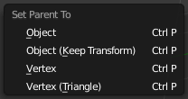
To parent objects, select at least two objects (select the Child Objects first, and select the Parent Object last), and press CtrlP. The Set Parent To dialog will pop up allowing you to select from one of several possible different parenting types. Selecting one of the entries in Set Parent To confirms, and the child/children to parent relationship is created.
The last object selected will be the Active Object (outlined in light orange), and will also be the Parent Object. If you selected multiple objects before selecting the parent, they will all be children of the parent and will be at the same level of the hierarchy (they are “siblings”).
The Set Parent To popup dialog is context sensitive, which means the number of entries it displays can change depending on what objects are selected when the CtrlP shortcut is used.
For non-inverse-mode, press ⇧ ShiftCtrlP instead. This creates an alternative parent-child-relationship where child-objects exist entirely in the parent's coordinate system. This is the better choice for CAD purposes, for example.
Moving, rotating or scaling the parent will also usually move/rotate/scale the child/children. However moving/rotating/scaling the child/children of the parent will not result in the parent moving/rotating/scaling. In other words, the direction of influence is from parent to child and not child to parent.
In general when using the CtrlP or [3D View Editor Header > Object Menu > Parent Menu] entires to parent objects, the Child Objects can only have one Parent Object. If a Child Object already has a Parent Object and you give it another parent then Blender will automatically remove the previous parent relationship.
Blender supports many different types of parenting, listed below:
- Object
- Object (Keep Transform)
- Armature Deform > With Empty Groups
- Armature Deform > With Automatic Weights
- Armature Deform > With Envelope Weights
- Bone
- Bone Relative
- Curve Deform
- Follow Path
- Path Constraint
- Lattice Deform
- Vertex
- Vertex (Triangle)
- Clear Parent
- Clear And Keep Transformation
- Clear Parent Inverse
Object Parent
Object Parent is the most general form of parenting that Blender supports. If will take selected objects and make the last selected object the Parent Object, while all other selected objects will be Child Objects.
Object (Keep Transform) Parent
Object (Keep Transform) Parent works in a very similar way to Object Parent the major difference is in weather the Child Objects will remember any previous transformations applied to them from the previous Parent Object.
Since explaining this in an easy to understand technical way is hard, lets instead use an example to demonstrate.
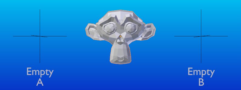
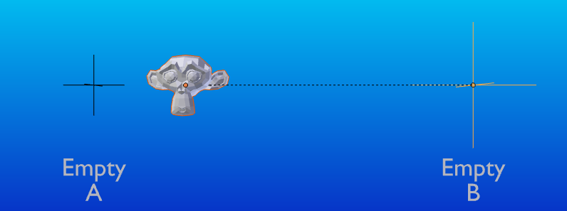
Assume that we have a scene consisting of 3 objects, those being 2 Empty Objects named "EmptyA" and "EmptyB", and a Monkey object. See figure 1.
Figure 1 shows the 3 objects with no parenting relationships active on them.
If you select the Monkey object by RMB ![]() click and then ⇧ ShiftRMB
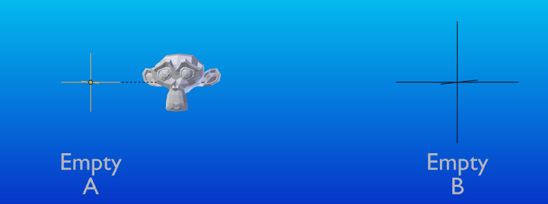
click and then ⇧ ShiftRMB ![]() click "EmptyA" object and press CtrlP and then select Object from the Set Parent To popup dialog box. This will result in "EmptyA" object being the Parent Object of the Monkey object. With only "EmptyA" selected rotating/scaling/moving it will result in the Monkey object being altered respectively.
click "EmptyA" object and press CtrlP and then select Object from the Set Parent To popup dialog box. This will result in "EmptyA" object being the Parent Object of the Monkey object. With only "EmptyA" selected rotating/scaling/moving it will result in the Monkey object being altered respectively.
Scale the "EmptyA" object, so that the Monkey becomes smaller and moves to the left a little. See figure 2.
If you select only the Monkey object by RMB ![]() click and then ⇧ ShiftRMB
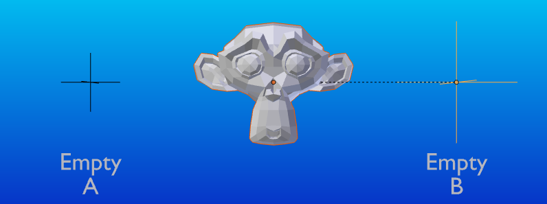
click and then ⇧ ShiftRMB ![]() click "EmptyB" object and press CtrlP and select Object from the Set Parent To popup dialog box. This will result in "EmptyB" object being the Parent Object of the Monkey object. Notice that when you change the parent of the Monkey the scale of the Monkey changed. See figure 3.
click "EmptyB" object and press CtrlP and select Object from the Set Parent To popup dialog box. This will result in "EmptyB" object being the Parent Object of the Monkey object. Notice that when you change the parent of the Monkey the scale of the Monkey changed. See figure 3.
This happens because the Monkey object never had its scale altered directly, the change came about because it was the child of "EmptyA" which had its scale altered. Changing the Monkey's parent to "EmptyB" resulted in those indirect changes in scale being removed, because "EmptyB" has not had its scale altered.
This is often the required behaviour, but it is also sometimes useful that if you change your Parent Object that the Child Object keep any previous transformations it got from the old Parent Object; If instead when changing the Parent Object of the Monkey from "EmptyA" to "EmptyB" we had chosen parenting type Object (Keep Transform), the Monkey would keep its scale information it obtained from the old parent "EmptyA" when it is assigned to the new parent "EmptyB"; See Figure 4.
If you want to follow along with the above description here is the blend file used to describe Object (Keep Transform) parenting method:
ファイル:Parent - Object (Keep Transform) (Demo File).blend
Armature Deform Parent
An Armature in Blender can be thought of as similar to the armature of a real skeleton, and just like a real skeleton an Armature can consist of many bones. These bones can be moved around and anything that they are attached to or associated with will move and deform in a similar way.
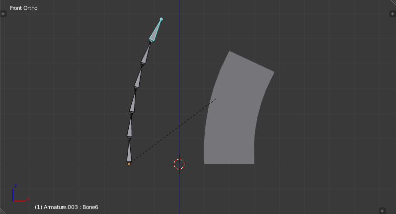
In Blender Armature Object Types are usually used to associate certain bones of an Armature to certain parts of a Mesh Object Types Mesh Geometry. You are then able to move the Armature Bones and the Mesh Object will deform. See figure 5.
Armature Deform Parenting is one of the most flexible ways of associating Bones in an Armature to another Object, it gives a lot of freedom but that comes at the price of a little complexity, as there are multiple steps involved in setting up Armature Deform Parenting such that deformations are actually carried out.
Blender has several different ways of Parenting an Armature to an object, most of them can automate several of the steps involved, but all of them ultimately do all the steps we describe for Armature Deform Parenting.
Using the Armature Deform Parenting operator is the first step in setting up the relationship between an Armature Object and it's Child Objects.
To use Armature Deform Parenting you must first select all the Child Objects that will be influenced by the Armature and then lastly select the Armature Object itself. Once all the Child Objects and the Armature Object are selected press CtrlP and select Armature Deform in the Set Parent To popup dialog. See figure 6.
Once this is done the Armature Object will be the Parent Object of all the other Child Objects, also we have informed Blender that the Bones of the Armature Object can be associated with specific parts of the Child Objects so that they can be directly manipulated by the Bones.
At this point however all Blender knows is that the Bones of the Armature could be used to alter the Child Objects, we haven't yet told Blender which Bones can alter which Child Objects or by how much.
To do that we must individually select each Child Object individually and toggle into Edit Mode on that Child Object. Once in Edit Mode we can then select the vertices we want to be influenced by the Bones in the Armature. Then with the vertices still selected navigate to [Properties Editor > Object Data Context > Vertex Groups Panel] and create a new Vertex Group with the same name as the Bone that you want the selected vertices to be influenced by.
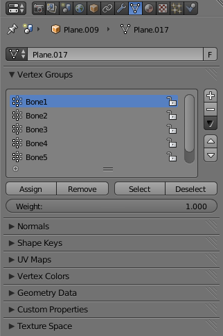
Once the Vertex Group has been created we then assign the selected vertices to the Vertex Group by clicking the Assign Button. By default when selected vertices are assigned to a Vertex Group they will have an Influence Weight of 1. This means that they are fully influenced when a Bone they are associated with is moved, if the Influence Weight had been .5 then when the bone moves the vertices would only move half as much. See figure 7.
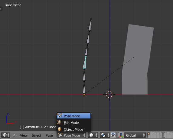
Once all these steps have been carried out, the Bones of the Armature Object should be associated with the Vertex Groups with the same names as the Bones. You can then select the Armature Object and switch to Pose Mode in the [3D View Editor Header > Mode Select Button]. See figure 8.
Once in Pose Mode transforming one of the Bones of the Armature that has been associated with vertices of an object will result in those vertices also being transformed.
Armature Deform Parenting - Example Of Use
What follows is a simple example of how to setup Armature Deform Parenting so that you end up with an Armature whose Bones can Influence the mesh of a Child Object when the Armature is in Pose Mode.
- Open Blender with it's Default Scene.
- Switch the 3D Viewport to Front View by pressing Numpad1.
- Select the Default Cube and delete it by pressing the X.
- Add a Plane Object by pressing the Spacebar and entering "add plane" into search text field. Then press the ↵ Enter or LMB
 the listed Add Plane entry.
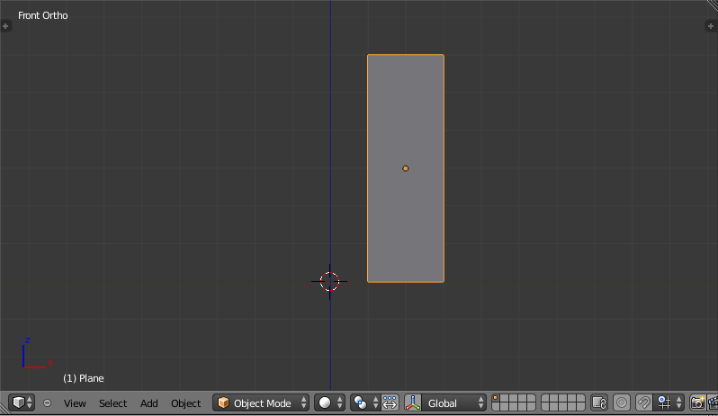
 - While in Object Mode and with the Plane Object still selected we need to rotate it on x axis by 90 degrees, so that its face points towards the front view. To do this by pressing the R then X then enter the value 90.
- Scale the Plane along the Z axis by a factor of 3. Do this by pressing the S then the Z then enter the value 3.
- With the Plane still selected and still in Object Mode move it upward 3 Blender Units along the Z axis. Do this by pressing G then Z then enter the value 3.
- Move the Plane along the X axis to the right by 2 Blender Units. Do this by pressing the G then X then enter the value 2.
- If you are following along your scene should look similar to figure 9.
- With the Plane still selected toggle into Edit Mode by pressing ⇆ Tab until Edit Mode is displayed in the [3D View Editor Header > Mode Select Button].
- Now make sure all the vertices of the Plane are selected by pressing the A repeatedly until all the vertices are selected (highlighted in orange).
- With all the vertices selected we now need to tell Blender to split the face of the Plane up into 6 equal sized faces. We can do this by using Blender's Loop Cut tool.
- Active the Loop Cut tool by pressing CtrlR while the mouse is over the Plane object in the 3D Viewport.
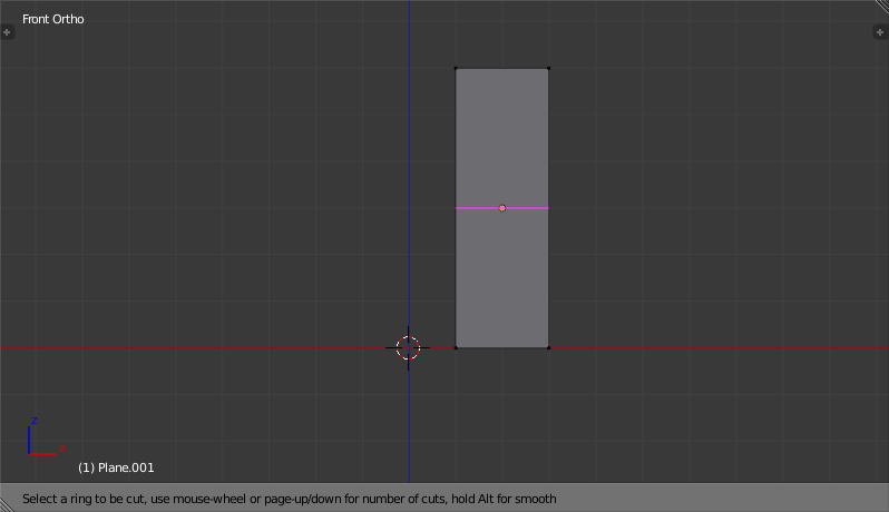
- Position the mouse over the middle section of the Plane. Depending on where you position the mouse over the Plane, there will be a thin pink line drawn either vertically or horizontally along the Plane.
- Position the mouse such that a single horizontal pink line is displayed at the center of the Plane. See figure 10.
- With the pink line still displayed enter the value 5 then press the ↵ Enter twice, without moving the mouse.
- If done correctly you should now have a Plane that is sectioned into 6 horizontal faces. See figure 11.
- With the Plane still selected Toggle into Object Mode by pressing the ⇆ Tab repeatedly until Object Mode is displayed in the [3D View Editor Header].
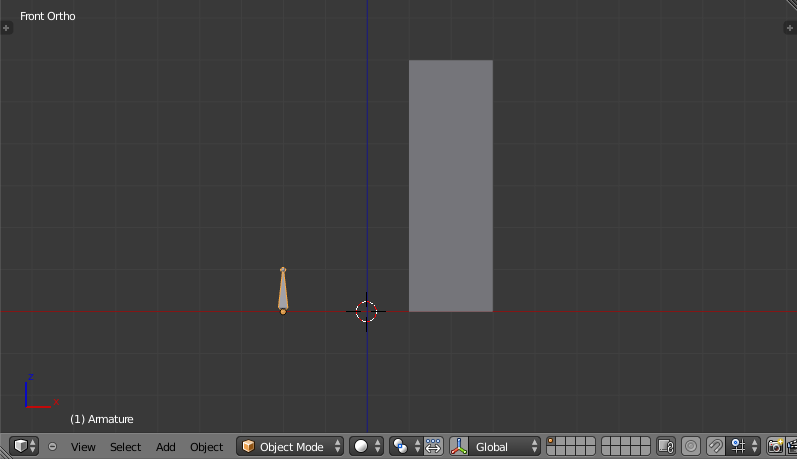
- In Object Mode add an Armature Object. Do this by positioning the mouse over the 3D Viewport then activating the Add Menu ⇧ ShiftA selecting the Armature entry and selecting the Single Bone entry.
- Move the Armature to the left along the X axis by 2 Blender Units. Do this by selecting the Armature, pressing the G then X then enter the value -2.
- If you were following along you should have a scene that looks similar to figure 12.
- With the Armature still selected switch into Edit Mode by pressing the ⇆ Tab and toggling into Edit Mode.
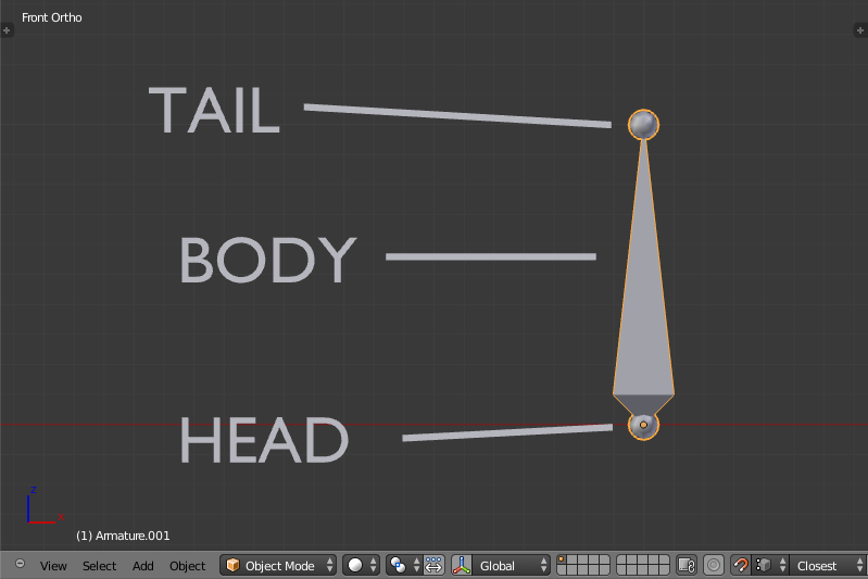
- The Armature Bone will display differently when it is in Edit Mode. See figure 13.
- The Armature Bone in Edit Mode has 3 distinct parts, The Head (thick bottom part), The Body (the middle part) and The Tail (the top pointy part).
- Select The Tail of the Bone so that it is the only thing highlighted.
- Extrude the Bone Tail by 1 Blender Unit along the Z axis. Do this by pressing the E then the Z and enter the value 1. This will extrude a new Bone from The Tail of the previous Bone.
- Repeat the extruding from The Tail of the new bones 4 times by pressing ⇧ ShiftR 4 times. The ⇧ ShiftR executes the Repeat Last command operator.
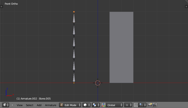
- You should now have an Armature with 6 bones in it, each emerging from The Tail of the previous bone.
- If you have been following along you should have a scene that looks similar to figure 14.
- While still in Edit Mode select the body of the first bone of the Armature we created. If selected correctly the entire bone will be highlighted, not just the head or tail.
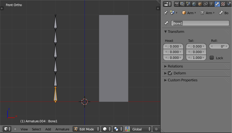
- Navigate to the [Properties Editor > Bone Context > Bone Text Field] and change the name of the bone from Bone to Bone1. See figure 15.
- Do the same for all the other bones in the Armature naming them Bone2, Bone3, Bone4, Bone5 and Bone6 respectively.
- Note that Blender is case sensitive when it comes to naming of objects such as bones, so make sure to name them consistently as Blender does not consider Bone or bone the same.
- Once the bones have been renamed, toggle Blender into Object Mode by pressing the ⇆ Tab.
- Now we need to make the Plane the Child Object of the Armature. To do this select only the Plane then ⇧ ShiftRMB
 the Armature.
 - With the Plane and the Armature selected activate the Set Parent To popup dialog by pressing CtrlP and select the Armature Deform entry.
- This should result in the Armature being the Parent Object of the Plane.
- So at this point we have renamed all six bones of the Armature Bone1, Bone2, Bone3, Bone4, Bone5 and Bone6. We have split a single Plane into 6 faces and scaled it to match the total length of the Armature Bones. We then made the Plane the Child Object of the Armature using the CtrlP Armature Deform Parenting option.
- The final step is to associate the different bones of the Armature to the different vertices that make up the faces of the Plane, so that moving the bones, actually moves the faces.
- To do that we need to select the vertices we want to associate with a particular bone and then create a Vertex Group with the same name as the bone and then assign the selected vertices to that Vertex Group.
- Make sure the Plane is the only object that is selected.
- Switch into Edit Mode if we are not already by pressing the ⇆ Tab.
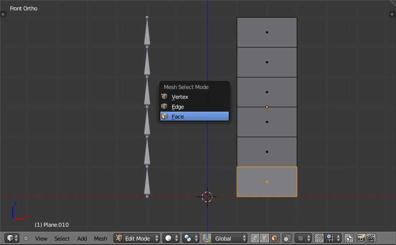
- Switch to Face Selection Mode by pressing Ctrl⇆ Tab and select Face from the Mesh Select Mode popup dialog. See figure 16.
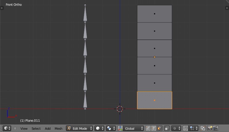
- Select the 1st face of the Plane by RMB
 it. See figure 17.
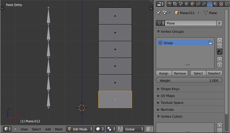
 - Navigate to the [Properties Editor > Object Data > Vertex Groups Panel] and click the + button to the right of the Vertex Groups list. See figure 18.
- This will create a new Vertex Group called Group.
- Rename this newly created Group to Bone1 by CtrlLMB
 on the Group name in the Vertex Group list and then typing in the new name. To complete the naming press the ↵ Enter.
 - Click the button named Assign to assign the currently selected face to that Vertex Group you just made and named Bone1.
- At this point if all went well you will have associated the 1st face of the Plane with Bone1 of the Armature.
- To associate the other faces 2 through 6 to the Armature Bones 2 through 6 you do the same things; Select the face, create a Vertex Group with the same name as the bone you want to associate the face with and then click the Assign button to associate the selected face with the selected Vertex Group.
- Toggle into Object Mode by pressing the ⇆ Tab.
- Now select only the Armature by RMB
 it.
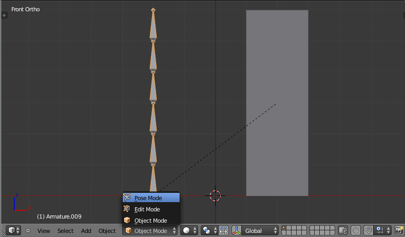
it. - Now we need to switch the Armature to Pose Mode. Do that by navigating to [3D View Editor Header > Mode Select Button] and LMB
 it and select the Pose Mode entry. See figure 19.
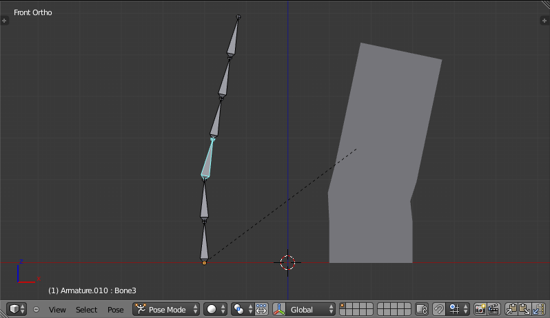
 - Now if you select the third bone (Bone3) in the Armature you will notice it gets highlighted in a Cyan color when in Pose Mode.
- If you transform that bone in anyway the associated face on the Plane will also transform in a similar way.
- For example rotate Bone3 and face section 3 will rotate in a similar way on the Plane. See figure 20.
Armature Deform Parent With Empty Groups
The Armature Deform With Empty Groups parenting method works in almost the same way as Armature Deform parenting with one difference. That difference is that when you parent a Child Object to an Armature Object the names of the bones in the armature are copied to the Child Objects in the form of newly created Vertex Groups, one for each different deforming armature bone name. The newly created Vertex Groups will be empty this means they will not have any vertices assigned to those Vertex Groups. You still must manually select the vertices and assign them to a particular Vertex Group of your choosing to have bones in the armature influence them.
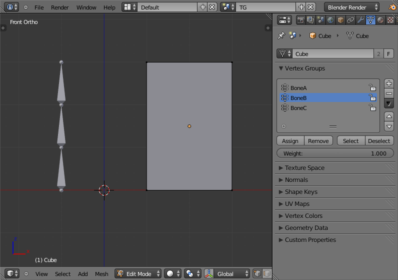
For example if you have an Armature Object which consists of 3 bones named BoneA, BoneB and BoneC and Cube Mesh Object type called Cube. If you parent the Cube Child Object to the Armature Parent Object the Cube will get 3 new Vertex Groups created on it called BoneA, BoneB and BoneC. Notice that each Vertex Group is empty. See figure 21.
Bones in an Armature can be generally classified into 2 different types:
- Deforming Bones
- Control Bones
Deforming Bones - Are bones which when transformed will result in vertices associated with them also transforming in a similar way. Deforming Bones are directly involved in altering the positions of vertices associated with their bones.
Control Bones - Are Bones which act in a similar way to switches, in that they control how other bones or objects react when they are transformed. A Control Bone could for example act as a sliding switch control, when the bone is in one position to the left it could indicate to other bones that they react in a particular way when transformed, when the Control Bone is positioned to the right, transforming other bones or objects could do something completely different. Control Bones are not directly used to alter the positions of vertices, in fact Control Bones often have no vertices directly associated with themselves.
When using the Armature Deform With Empty Groups parenting method Vertex Groups on the Child Object will only be created for Armature Bones which are setup as Deforming Bone types. If a Bone is a Control Bone no Vertex Group will be created on the Child Object for that bone.
To check weather a particular bone in an armature is a Deforming Bone simply switch to Pose Mode or Edit Mode on the armature and select the bone you are interested in by RMB ![]() it. Once the bone of interest is selected navigate to [Properties Editor > Bone Context > Deform Panel] and check if the Deform tickable option is ticked or not. If it is the selected bone is a Deforming Bone, otherwise it is a Control Bone. See figure 22.
it. Once the bone of interest is selected navigate to [Properties Editor > Bone Context > Deform Panel] and check if the Deform tickable option is ticked or not. If it is the selected bone is a Deforming Bone, otherwise it is a Control Bone. See figure 22.
Armature Deform With Automatic Weights
Armature Deform With Automatic Weights parenting feature does everything Armature Deform With Empty Groups does with one extra thing. That extra thing is that unlike Armature Deform With Empty Groups which leaves the automatically created Vertex Groups empty with no vertices assigned to them; Armature Deform With Automatic Weight will try to calculate how much Influence Weight a particular Armature Bone would have on a certain collection of vertices based on the distance from those vertices to a particular Armature Bone.
Once Blender has calculated the Influence Weight vertices should have it will assign that Influence Weight to the Vertex Groups that were previously created automatically by Blender on the Child Object when Armature Deform With Automatic Weights parenting command was carried out.
If all went well it should be possible to select the Armature Object switch it into Pose Mode and transform the bones of the Armature and the Child Object should deform in response. Unlike Armature Deform parenting you won't have to create Vertex Groups on the Child Object, neither will you have to assign Influences Weights to those Vertex Groups, Blender will try to do it for you.
To activate Armature Deform With Automatic Weights you must be in Object Mode or Pose Mode, then select all the Child Objects (usually Mesh Object Types) and lastly select the Armature Object; Once done press CtrlP and select the Armature Deform With Automatic Weights from the Set Parent To popup dialog.
This method of parenting is certainly easier setup but it can often lead to Armatures which do not deform Child Objects in ways you would want, as Blender can get a little confused when it comes to determining which Bones should influence certain vertices when calculating Influence Weights for more complex armatures and Child Objects. Symptoms of this confusion are that when transforming the Armature Object in Pose Mode parts of the Child Objects don't deform as you expect; If Blender does not give you the results you require you will have to manually alter the Influence Weights of vertices in relation to the Vertex Groups they belong to and have influence in.
You can easily check how much Influence Weight an Armature Bone has over vertices in 2 ways:
- Using the [3D View Editor > Properties Region > Vertex Weights Panel].
- Using Weight Paint Mode.
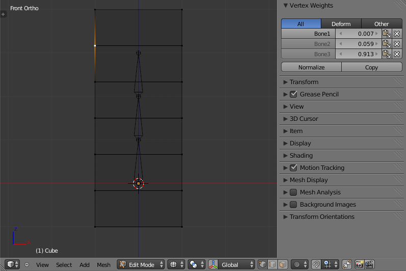
[3D View Editor > Properties Region > Vertex Weights Panel] - Allows you to see which Vertex Groups a particular vertex is a member of and how much Influence Weight that vertex has in the different Vertex Groups that it is a member of. Remember that Vertex Groups that have the same name as an Armatures Bones will be influenced by the bones in the Armature with the matching names. See figure 23.
Weight Paint Mode - Allows you to see the Influence Weights that Vertex Groups have on a particular objects mesh. If does this by color coding a mesh with various colors; These colors represent Influence Weights assigned to certain Vertex Groups.
When a mesh is displayed in Weight Paint Mode, parts of a mesh colored dark blue represent areas of a mesh that are not influenced by a certain Vertex Group, while those parts of the mesh displayed in bright red are influenced by certain Vertex Groups.
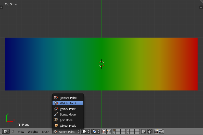
Red represents an Influence Weight of 1, blue represents and Influence Weight of 0, and all other colors represent Influence Weights between the 2 values. See figure 24.
To active Weight Paint Mode select the object you want to see in Weight Paint Mode by LMB ![]() it, then navigate to [3D View Editor Header > Mode Select Button] and select the Weight Paint entry. See figure 25.
it, then navigate to [3D View Editor Header > Mode Select Button] and select the Weight Paint entry. See figure 25.
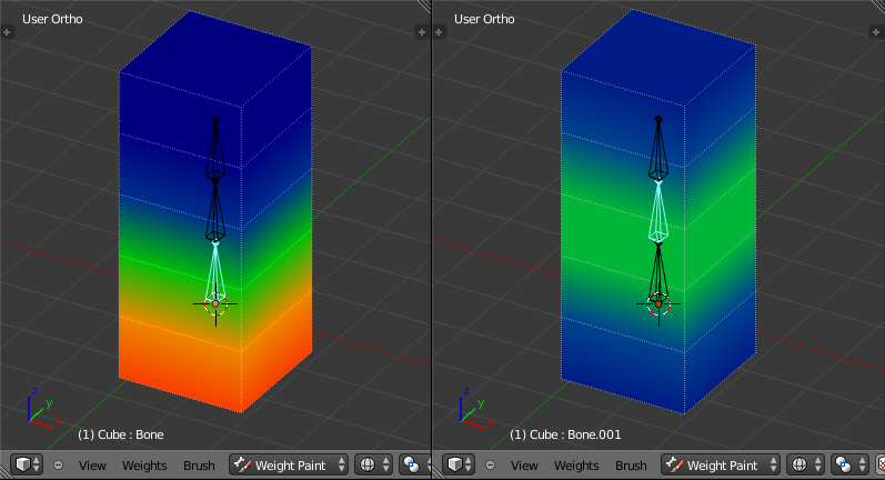
When Weight Paint Mode is used on a Mesh Object which is also the Child Object of an armature, clicking on a bone in the armature will shown the Influence Weight of the selected bone in Pose Mode. See figure 26.
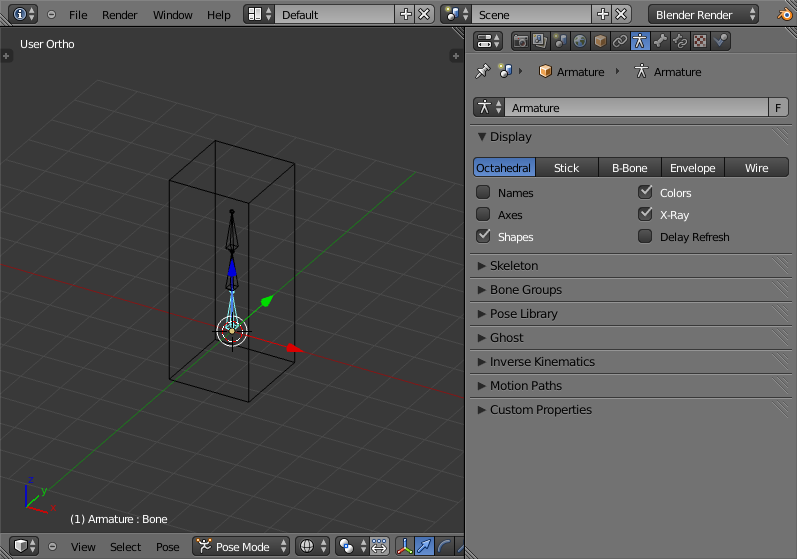
In Weight Paint Mode often you will find that the Armature Bones are obscured from view making them difficult to select; If this happens make sure that only the Armature Object is selected then navigate to [Properties Editor > Object Data Context > Display Panel] and make sure to enable the X-Ray tickable option. This will ensure that the Armature Bones are always visible even when Weight Paint Mode is active and a bone is inside a mesh. See figure 27.
If you find that a Child Object is deforming strangely when the Armature Bones are manipulated in Pose Mode, using Weight Paint Mode to see visually which parts of a mesh are influenced by a bone is a quick way to try and narrow down which bone is causing the problem.
Armature Deform With Envelope Weights
Works in a similar way to Armature Deform With Automatic Weights in that it will create Vertex Groups on the Child Objects that have names matching those of the Parent Object Armature Bones. The created Vertex Groups will then be assigned Influence Weights. The major difference is in the way those Influence Weights are calculated.
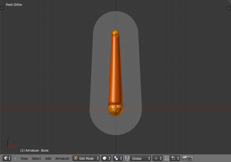
Influence Weights that are calculated when using Armature Deform With Envelope Weights parenting are calculated entirely visually using Bone Envelopes. See figure 28.
Figure 28 shows a single Armature Bone in Edit Mode with Envelope Weight activated. The gray semi-transparent volume around the bone is the Bone Envelope.
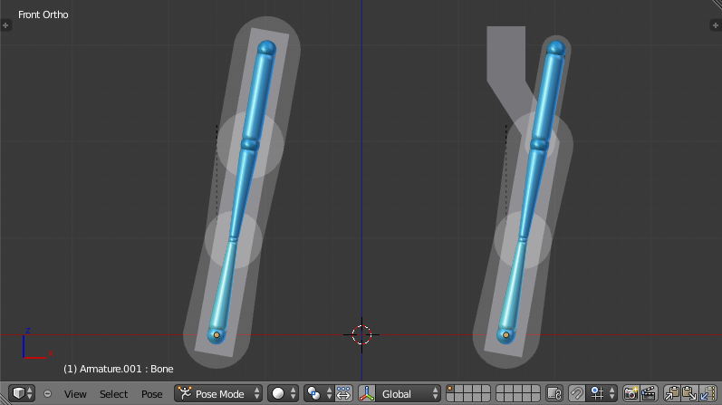
Any Child Object that has vertices inside the volume of the Bone Envelope will be influenced by the Parent Object Armature when the Armature Deform With Envelope Weights operator is used. Any vertices outside the Bone Evelope volume will not be influenced. See figure 29.
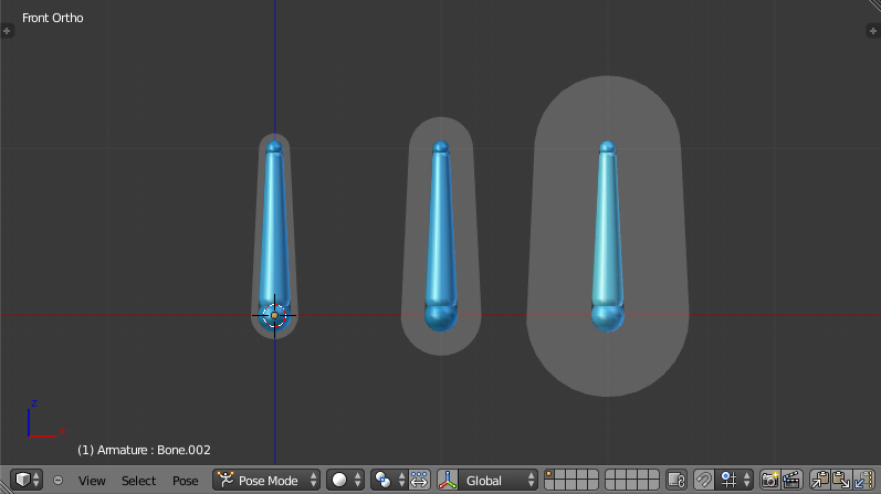
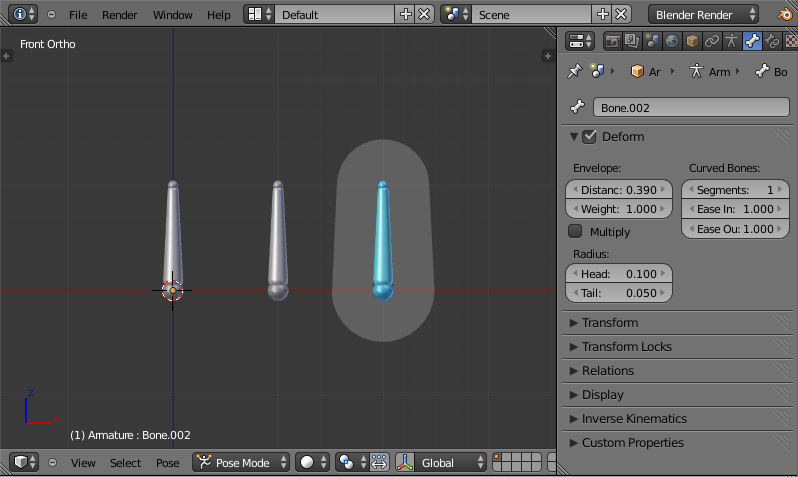
The default size of the Bone Envelope volume does not extend very far from the surface of a bone; You can alter the size of the Bone Envelope volume by clicking on the body of the bone you want to alter, switch to Edit Mode or Pose Mode and then pressing CtrlAltS then drag your mouse left or right and the Bone Envelope volume will alter accordingly. See figure 30.
You can also alter the Bone Envelope volume by selecting the Bone you wish to alter and switching to Edit Mode or Pose Mode, then navigate to [Properties Editor > Bone Context > Deform Panel > Envelope Section > Distance field] then enter a new value into it. See figure 31.
Altering the Bone Envelope volume does not alter the size of the Armature Bone just the range within which it can influence vertices of Child Objects.
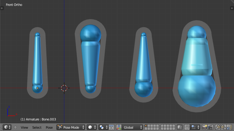
You can alter the radius that a bone has by selecting the head, body or tail parts of a bone while in Edit Mode, and then press AltS and move the mouse left or right. This will make the selected bone fatter or thinner without altering the thickness of the Bone Envelope volume. See figure 32.
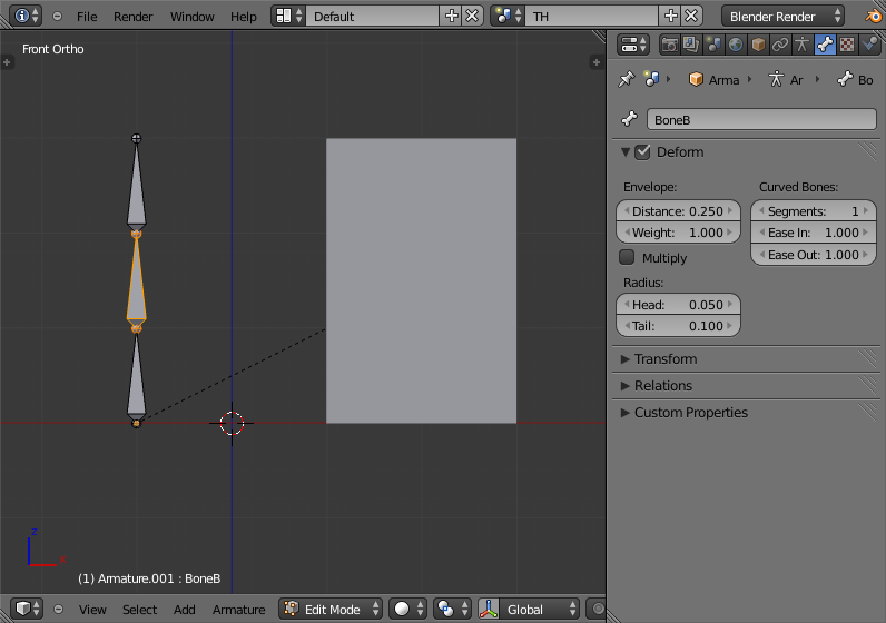
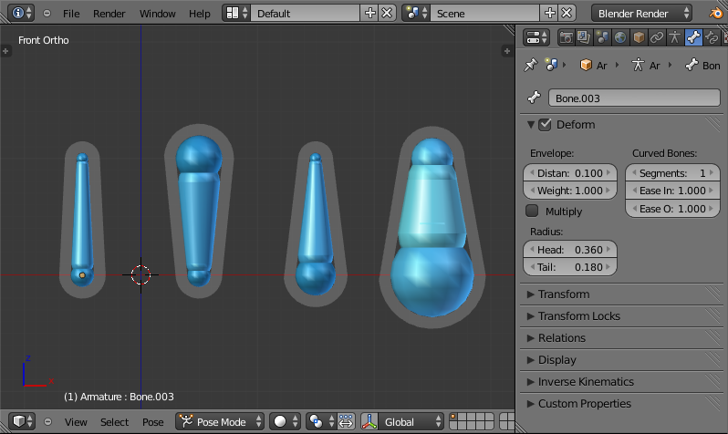
You can also alter the bone radius by selecting the tail or head of the bone you wish to alter and switching to Edit Mode, then navigate to [Properties Editor > Bone Context > Deform Panel > Radius Section] and entering new values for the Tail and Head fields. See figure 33.
| Note | |
| If you alter the Bone Envelope volume of a bone so that you can have it include/exclude certain vertices after you have already used Armature Deform With Envelope Weights, by default the newly included/excluded vertices wont be effected by the change. When using Armature Deform With Envelope Weights it only calculates which vertices will be affected by the Bone Envelope volume at the time of parenting, at which point it creates the required named Vertex Groups and assigns vertices to them as required. If you want any vertices to take account of the new Bone Envelope volume size you will have carry out the Armature Deform With Envelope Weights parenting again; In fact all parenting used in the Set Parent To popup dialog which tries to automatically assign vertices to Vertex Groups works like this. |
Bone Parent
Bone parenting allows you to make a certain bone in an armature the Parent Object of another object. This means that when transforming an armature the Child Object will only move if the specific bone it is the Child Object of moves. See figure 34.
To use Bone Parenting, you must first select all the Child Objects you wish to parent to a specific Armature Bone, then [SHIFT Key+Right Mouse Button Click] select the Armature Object and switch it into Pose Mode and then select the specific bone you wish to be the Parent Bone by [Right Mouse Button Click] it. Once done press [CTRL Key+P Key] and select Bone from the Set Parent To popup dialog.
Now transforming that bone in Pose Mode will result in the Child Objects also transforming.
Bone Parenting - Example Of Use
- Start Blender with it's default scene.
- Switch to Front View in the 3D Viewport by pressing [NUMPAD 1 Key].
- Move the default cube 3 Blender Units to the left on the X axis by pressing [G Key] then [X Key] then input value -3.
- With the default cube moved, add an Armature Object. Do this by pressing [SHIFT Key+A Key] to display the Add popup menu, navigate to the Armature entry and select Single Bone.
- With only the single Armature Bone selected switch into Edit Mode by pressing the [TAB Key].
- Select the top pointy end of the bone (the Tail).
- Extrude a new bone from the tail of the old bone that is 1 Blender Unit in length along the Z axis. Do this by pressing the [E Key] then the [Z Key] then input the value 1, then press the [ENTER Key].
- Create 2 more bones each extruding out of the Tail of the previous bone. Do this by pressing [SHIFT Key+R Key] twice; This will execute the Repeat Last command operator.
- Switch back into Object Mode by pressing the [TAB Key].
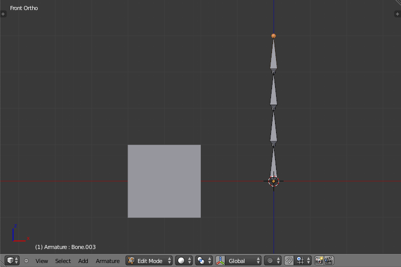
- You should now have a default cube and an Armature Object with 4 bones positioned as shown in figure 35].
- Select the default cube only and then [SHIFT Key+Right Mouse Button Click] the Armature Object.
- With the Cube and the Armature Object still selected navigate to [3D View Editor Header > Mode Select Button] and switch to Pose Mode.
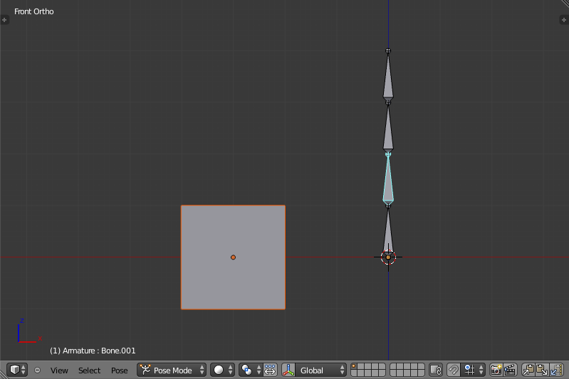
- [Right Mouse Button Click] on the second bone in the Armature Object, such that it becomes highlighted in Cyan. See figure 36.
- Now we need to make that selected Armature Bone the Parent Bone of the Cube Child Object. To do that activate the Set Parent To popup dialog by pressing [CTRL Key+P Key] and selecting the Bone entry from the popup.
- Once done switch back into Object Mode and select only the Armature Object.
- Now if you switch the Armature Object back into Pose Mode and transform the 3rd or 4th bones of the armature the Cube Child Object is not affected, but if you transform the 1st or 2nd bones it is because altering either of those bones results in the 2nd bone being transformed.
Bone Relative Parenting
Bone Relative parenting works in the same way as Bone parenting with one difference.
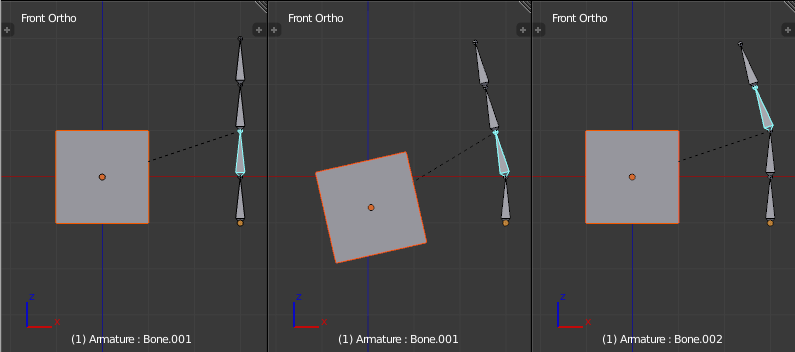
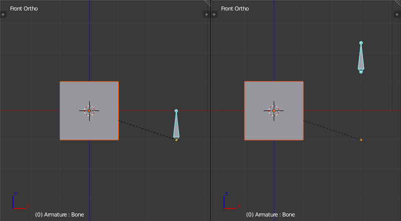
With Bone parenting if you have parented a bone to some Child Objects and you select that bone and switch it into Edit Mode and then translate that bone; When you switch back into Pose Mode on that bone, the Child Object which is parented to that bone will snap back to the location of the bone in Pose Mode. See figure 37.
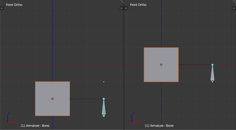
Bone Relative parenting works differently; If you move a Parent Bone in Edit Mode, when you switch back to Pose Mode, the Child Objects will not move to the new location of the Pose Bone. See figure 38.
Vertex Parent
You can parent an object to a single vertex or a group of three vertices as well; that way the child/children will move when the parent mesh is deformed, like a mosquito on a pulsing artery.
Vertex Parent from Edit Mode
In Object mode, select the child/children and then the parent object. ⇆ Tab into Edit mode and on the parent object select either one vertex that defines a single point, or select three vertices that define an area (the three vertices do not have to form a complete face; they can be any three vertices of the parent object), and then hit CtrlP and confirm.
At this point, if a single vertex was selected, a relationship/parenting line will be drawn from the vertex to the child/children. If three vertices were selected then a relationship/parenting line is drawn from the averaged center of the three points (of the parent object) to the child/children. Now, as the parent mesh deforms and the chosen parent vertex/vertices move, the child/children will move as well.
Vertex Parent from Object Mode
Vertex parenting can be performed from object mode, This is done like regular object parenting, Press CtrlP in object mode and select Vertex or Vertex (Triangle).
The nearest vertices will be used from each object which is typically what you would want.
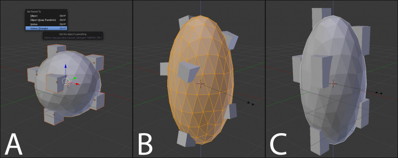
B) Reshaping the object in edit mode then means each of the cubes follows their vertex triad parent separately.
C) Re-scaling the parent icosphere in object mode means the child cubes are also rescaled as expected.
The parent context menu item means users can rapidly set up a large number of vertex parent relationships, and avoid the tedious effort of establishing each parent-child vertex relationship separately.
Note
It is in fact a sort of “reversed” hook
|
Options
Move child
You can move a child object to its parent by clearing its origin. The relationship between the parent and child isn’t affected. Select the child object and press AltO. By confirming the dialog the child object will snap to the parent’s location. Use the Outliner view to verify that the child object is still parented.
Remove relationship/Clear Parent
You can remove a parent-child relationship via AltP
The menu contains:
- Clear Parent
- If the parent in the group is selected nothing is done. If a child or children are selected they are disassociated from the parent, or freed, and they return to their original location, rotation, and size.
- Clear and Keep Transformation
- Frees the children from the parent, and keeps the location, rotation, and size given to them by the parent.
- Clear Parent Inverse
- Places the children with respect to the parent as if they were placed in the Global reference. This effectively clears the parent’s transformation from the children. For example, if the parent is moved 10 units along the X axis and Clear Parent Inverse is invoked, any selected children are freed and moved -10 units back along the X axis. The “Inverse” only uses the last transformation; if the parent moved twice, 10 units each time for a total of 20 units, then the “Inverse” will only move the child back 10 units, not 20.
Parenting Example
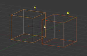
The active object, in yellow (cube A), will be made the parent of all the other object(s) in the group (orange cube B). The center(s) of all children object(s) are now linked to the center of the parent by a dashed line; see image (Parenting Example). The parent object is cube “A” and the child object is cube “B”. The link is labeled “L”.
At this point, grabbing, rotating, and scaling transformations to the parent will do the same to the children. Parenting is a very important tool with many advanced applications, as we’ll see in later chapters; it is used extensively with advanced animations.
Hints
There is another way to see the parent-child relationship in groups and that is to use the Outliner view of the Outliner window. Image (Outliner view) is an example of what the Outliner view looks like for the (Parenting Example). Cube “A”’s object name is “Cube_Parent” and cube “B” is “Cube_Child”.
Separating Objects
At some point, you’ll come to a time when you need to cut parts away from a mesh to be separate. Well, the operation is easy.
To separate an object, the vertices (or faces) must be selected and then separated, though there are several different ways to do this. In Edit Mode, press P then select one of the following.
Options
- Selected
- This option separates the selection to a new object.
- All Loose Parts
- Separates the mesh in its unconnected parts.
- By Material
- Creates separate mesh objects for each material.
Grouping objects
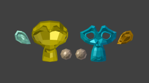
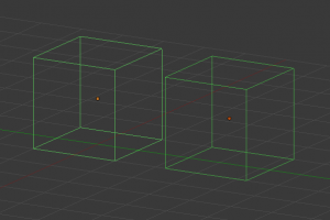
Group objects together without any kind of transformation relationship. Use groups to just logically organize your scene, or to facilitate one-step appending or linking between files or across scenes. Objects that are part of a group always shows as light green when selected; see image (Grouped objects).
Options
- Creating a Group
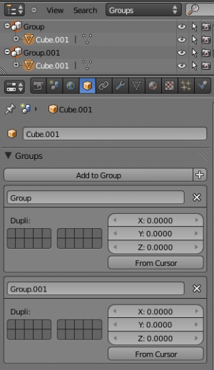
- CtrlG creates a new group and adds the selected object(s) to it.
- Naming a Group
- All groups that an objects have been assigned to are listed in the Object Properties Panel's Relations panel. To rename a group, simply click in the groups name field.
- To name groups in the Outliner window, select Groups as the outliner display from the header combo box, and CtrlLMB
 click on the group name. The name will change to an editable field; make your changes and press ↵ Enter.
 - Restricting Group Contents via Layers
- The cluster of layer buttons attached to each group determines from which layers the group objects will be included when duplicated. If your group contains objects on layers 10, 11 and 12, but you disable the layer 12 button in the group controls, duplicates of that group (using the Dupligroup feature) will only show the portions of the group that reside in layers 10 and 11.
- Appending or Linking Groups
- To append a group from another .blend file, consult this page. In summary, File → Append or Link →
filename→ Group →groupname.
Select Grouped
Mode: Object mode
Hotkey: ⇧ ShiftG
Menu: Select → Grouped
Select objects by parenting and grouping characteristics.
See Select Grouped for more information.
目次
[非表示]- 1 Grouping And Parenting Objects
- 2 Parenting objects
- 2.1 Object Parent
- 2.2 Object (Keep Transform) Parent
- 2.3 Armature Deform Parent
- 2.4 Armature Deform Parenting - Example Of Use
- 2.5 Armature Deform Parent With Empty Groups
- 2.6 Armature Deform With Automatic Weights
- 2.7 Armature Deform With Envelope Weights
- 2.8 Bone Parent
- 2.9 Bone Parenting - Example Of Use
- 2.10 Vertex Parent
- 2.11 Options
- 2.12 Parenting Example
- 2.13 Hints
- 3 Separating Objects
- 4 Grouping objects
