Doc:2.6/Manual/Animation/Basics/Drivers
目次
Drivers
Drivers

Drivers can use properties, numbers, transformations, and scripts, to control the values of properties.
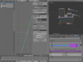
Using a F-Curve, the driver reads the value of the Driver Value and sets the value of the selected property it was added to.
So from this example, if the Driver Value is 2.0 the property will be 0.5.
The Driver Value is determined by Driver Variables or a Scripted Expression.
Most the settings for the drivers F-Curves are found in the Graph Editor.
Drivers Panel

- This panel is located in the Graph Editor with the mode set to Drivers.
- The drivers panel is for setting up Driver Variables or a Scripted Expression which will determine the value of the Driver Value.
Driver Settings
- Update Dependencies
- This will force an update for the Driver Value dependencies.
- Remove Driver
- Removes the driver from the object.
- Type
- The type of calculation to use on the set of Driver Variables. (If you only have one driver variable there is no real difference between average, sum, minimum and maximum)
- Average Value
- Uses the the average value of the referenced Driver Variables.
- Sum Values
- Uses the the sum of the referenced Driver Variables.
- Scripted Expression
- Uses a Scripted Expression. See Expr.
- You must write a python expression which performs your own calculations on the Driver Variables.
- Minimum Value
- Uses the lowest value from the referenced Driver Variables.
- Maximum Value
- Uses the highest value from the referenced Driver Variables.
- Expr
- Scripted Expression.
- Here you can add real numbers, math operators, math functions, python properties, driver functions.
- See Driver Expression below for some examples.
- Show Debug Info
- Shows the Driver Value.
- The current value of the variables or scripted expression.
- Add Variable
- Adds a new Driver Variable.


Driver Variables
- Name
- Name to use for scripted expressions/functions.
- No spaces or dots are allowed and must start with a letter.
- Variable Type
- The type of variable to use.
- Single Property
- Use the value from some RNA property.
- For example, the Ambient shading color from a material.
- First select the type of ID-block, then the ID of the ID-block, then copy and paste an RNA property (Ctrl+V).
- ID-Type
- The ID-Block type, example, Key, Image, Object, Material.
- ID
- The ID of the ID-Block type, example, Material.001.
- RNA Path
- The RNA id name of the property, example, 'ambient' from material shading.
- Transform Channel
- Use one of the Transform channels from an object or bone.
- ID
- ID of the object, example, Cube, Armature, Camera.
- Bone
- ID of the Armature bone, example, Bone, Bone.002, Arma.r.
- This option is for armatures.
- Type
- Example, X Location, X Rotation, X Scale.
- Space
- World Space, Transform Space, Local Space.
- Rotational Difference
- Use the rotational difference between two objects or bones.
- Distance
- Use the distance between two objects or bones.
- Value
- Shows the value of the variable.
Workflow
Adding Drivers
- To control a property with a driver, find the property you want to add driver to.
- RMB
 the property and select one of the following options.
- Add Drivers
- This will add drivers to the set of properties related to the selected one.
- For example, it will add drivers to X, Y, and Z for Rotation.
- Add Single Driver
- This will add a single driver to the selected property.

Transform Driver
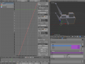
- This example shows you how rotate a cube mesh by moving another cube left or right in the 3D view.
- First make sure you are in the Front Orthographic View Num1, Num5.
- In Object Mode select then Duplicate ⇧ ShiftD the default Cube.
- Move the cube to a new location. You should have two mesh objects, Cube and Cube.001.
- With Cube.001 selected as the active object, Add Single Driver to the Rotation Y property.
- Open the Graph Editor, set the mode to Drivers.
- Show Only Selected is useful disabled for drivers, marked in green.
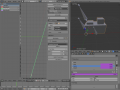
- Open the Properties Region N, go to the Drivers Panel.
- You may need to select the driver Y Euler Rotation LMB
 for the Drivers Panel to appear.
- You may need to select the driver Y Euler Rotation LMB
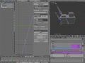
- Set the driver Type to Sum Values.
- Set the driver variable var settings.
- Set Type to Transform Channel.
- Set Ob/Bone ID-block to Cube.
- Set Transform Type to X Location.
- Set Transform Space to World Space.

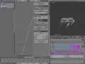
- Now when you move the Cube left or right in the 3D View, Cube.001 should rotate.
Examples
Some Driver Examples.
Driver Expression
Here are some examples using the scripted expression Expr to set the Driver Value.

Orbit a point
Here two drivers have been added to the Cube, X Location and Y Location.
The scripted expressions are being used to set the object location.
- X Location Expr
- 0+(sin(frame/8)*4)
- (frame/8): is the current frame of the animation, divided by 8 to slow the orbit down.
- (sin( )*4): This returns the sine of (frame/8), then multiplies by 4 for a bigger circle.
- 0+: is used to control the X Location offset of the orbit.
- Y Location Expr
- 0+(cos(frame/8)*4)
- (frame/8): is the current frame of the animation, divided by 8 to slow the orbit down.
- (cos( )*4): This returns the cosine of (frame/8), then multiplies by 4 for a bigger circle.
- 0+: is used to control the Y Location offset of the orbit.
frame is the same as bpy.context.scene.frame_current.
Driver Namespace
- There is a list of built in driver functions and properties.
- These can be displayed via the python console.
>>> bpy.app.driver_namespace['
                              __builtins__']
                              __doc__']
                              __loader__']
                              __name__']
                              __package__']
                              acos']
                              acosh']
                              asin']
                              asinh']
                              atan']
                              atan2']
                              atanh']
                              bpy']
                              ceil']
                              copysign']
                              cos']
                              cosh']
                              ..
- This script will add a function to the driver namespace, which can then be used in the expression driverFunc(frame).
import bpy

def driverFunc(val):

    return val * val    # return val squared

bpy.app.driver_namespace['driverFunc'] = driverFunc    # add function to driver_namespace
Shape Key Driver
- This example is a Shape Key Driver. The driver was added to the shape key Value.

- This example uses the Armature Bone 'b' Z Rotation to control the Value of a Shape Key.
- The bone rotation mode is set to XYZ Euler.
- The Driver F-Curve is mapped like so
- Bone Z Rotation 0.0(0.0): Shape Key value 0.0
- Bone Z Rotation -2.09(-120.0): Shape Key value 1.0
- This kind of driver can also be setup with the Variable Type Rotational Difference.
- See Shape Keys for more info.
Drivers And Multiple Relative Shape Keys
The following screenshots illustrate combining shape keys, bones, and drivers to make multiple chained relative shape keys sharing a single root. While it lacks the convenience of the single Evaluation Time of an absolute shape key, it allows you to have more complex relationships between your shape keys.
- Drivers and Multiple Shape Keys
Key1 must handle conflicting values from the two bones
Key2A has different generator coefficients so it is activated in a different range of the bone's position.
Key2B is the same as Key2A, but is controlled by the second bone.
when both bones are low, Key2B and Key2A are deactivated and Key1 is at low influence.


The Basis shape key has the stacks fully retracted. Key1 has the base fully extended. Key2A has the left stack fully extended. Key2B has the right stack fully extended. Key2A and Key2B are both relative to Key1 (as you can see in the field in the bottom right of the Shape Keys panel.
The value of Key1 is bound to the position of bones by a driver with two variables. Each variable uses the world Z coordinate of a bone and uses the maximum value to determine how much the base should be extended. The generator polynomial is crafted such that the top of the dominant stack should line up with the bone for that stack.
The value of Key2A is bound to the position of bone.L . Its generator parameters are crafted such that when Key1's value reaches 1, the value of Key2A starts increasing beyond zero. In this way the top of the left stack will move with bone.L (mostly).
The value of Key2B is bound to the position of bone.R . Its generator parameters are similar to Key2A so that the top of the right stack will move with bone.R (mostly).
Since it's quite easy for bone.L and bone.R to be in positions that indicate conflicting values for Key1 there will be times when the bones do not line up with the tops of their respective stacks. If the driver for Key1 were to use Average or Minimum instead of Maximum to determine the value of the shape key then "conflicts" between bone.L and bone.R would be resolved differently. You will chose according to the needs of your animation.
Troubleshooting
Some common problems people may run in to when using drivers.
Scripted Expression

- By default blender will not auto run python scripts.
- If using a Scripted Expression Driver Type, you will have to open the file as Trusted Source, or set Auto Run Python Scripts in User Preferences > File > Auto Execution.


Rotational Properties are Radians
Parts of the User Interface may use different units of measurements for angles, rotation. In the Graph Editor while working with Drivers, all angles are Radians.
Intra-armature Bone Drivers Can Misbehave
There is a well known limitation with drivers on bones that refer to another bone in the same armature. Their values can be incorrectly calculated based on the position of the other bone as it was before you adjust the current_frame. This can lead to obvious shape glitches when the rendering of frames has a jump in the frame number (either because the .blend file is currently on a different frame number or because you're skipping already-rendered frames).
See Also
Links
- Python and its documentation.
- functions.wolfram.com