Doc:2.6/Manual/Composite Nodes/Types/Color
Page status (reviewing guidelines)
Copy This page is a copy of the same page in 2.4 manual, need to be updated Text
The Gamma Node explanation is a mess
|
Composite Color Nodes
These nodes play with the colors in the image. They adjust the image's color intensity, adjust contrast and intensity, and, most importantly, mix two images together by color, transparency, or distance.
RGB Curves Node
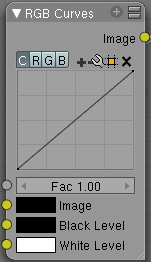
For each color component channel (RGB) or the composite (C), this node allows you to define a bezier curve that varies the input (across the bottom, or x-axis) to produce an output value (the y-axis). By default, it is a straight line with a constant slope, so that .5 along the x-axis results in a .5 y-axis output. Click and drag along the curve to create a control point and to change the curve's shape. Use the X to delete the selected (white) point.
Clicking on each C R G B component displays the curve for that channel. For example, making the composite curve flatter (by clicking and dragging the left-hand point of the curve up) means that a little amount of color will result in a lot more color (a higher Y value). Effectively, this bolsters the faint details while reducing overall contrast. You can also set a curve just for the red, and for example, set the curve so that a little red does not show at all, but a lot of red does.
Here are some common curves you can use to achieve desired effects:
Options
- Fac
- How much the node should factor in its settings and affect the output.
- Black Level
- Defines the input color that is mapped to black. Default is black, which does not change the image.
- White Level
- Defines the input color that is mapped to white. Default is white, which does not change the image.
The levels work exactly like the ones in the image viewer. Input colors are scaled linearly to match black/white levels.
To define the levels, either use LMB on the color patch to bring up the color selection widget or connect some RGBA input to the sockets.
To only affect the value/contrast (not hue) of the output, set the levels to shades of gray. This is equivalent to setting a linear curve for C.
If you set any level to a color with a saturation greater than 0, the output colors will change accordingly, allowing for basic color correction or effects. This is equivalent to setting linear curves for R, G and B.
Examples
Color correction using Curves
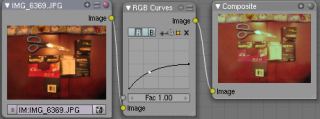
In this example, the image has way too much red in it, so we run it through an RGB node and reduce the Red channel by about half.
We added a middle dot so we could make the line into a sideways exponential curve. This kind of curve evens out the amount of a color in an image as it reaches saturation. Also, read on for examples of the Darken and Contrast Enhancement curves.
Color correction using Black/White Levels
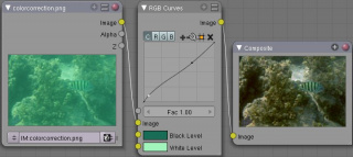
Manually adjusting the RGB curves for color correction can be difficult. Another option for color correction is to use the Black and White Levels instead, which really might be their main purpose.
In this example, the White Level is set to the color of a bright spot of the sand in the background, and the Black Level to the color in the center of the fish's eye. To do this efficiently it's best to bring up an image viewer window showing the original input image. You can then use the levels' color picker to easily choose the appropriate colors from the input image, zooming in to pixel level if necessary. The result can be fine-tuned with the R,G, and B curves like in the previous example.
The curve for C is used to compensate for the increased contrast that is a side-effect of setting Black and White Levels.
Effects
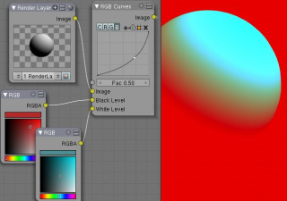
Curves and Black/White Levels can also be used to completely change the colors of an image.
Note that e.g. setting Black Level to red and White Level to blue does not simply substitute black with red and white with blue as the example image might suggest. Levels do color scaling, not substitution, but depending on the settings they can result in the described color substitution.
(What really happens when setting Black Level to pure red and White Level to pure blue is that the red channel gets inverted, green gets reduced to zero and blue remains unchanged.)
Because of this the results of setting arbitrary Black/White Levels or RGB curves is hard to predict, but can be fun to play with.
Mix Node
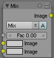
This node mixes a base image (threaded to the top socket) together with a second image (bottom socket) by working on the individual and corresponding pixels in the two images or surfaces. The way the output image is produced is selected in the drop-down menu. The size (output resolution) of the image produced by the mix node is the size of the base image. The alpha and Z channels are mixed as well.
Not one, not two, but count 'em, sixteen mixing choices include:
- Mix
- The background pixel is covered by the foreground using alpha values.
- Add
- The pixels are added together. Fac controls how much of the second socket to add in. Gives a bright result.
- The "opposite" to Subtract mode.
- Subtract
- Pixels are subtracted from one another. Gives a dark result.
- The "opposite" to Add mode.
- Multiply
- Returns a darker result than either pixel in most cases (except if one of them equals white=1). Completely white layers do not change the background at all. Completely black layers give a black result.
- The "opposite" to Screen mode.
- Screen
- Both pixel values are inverted, multiplied by each other, then the result is inverted again. This returns a brighter result than both input pixels in most cases (except if one of them equals 0). Completely black layers do not change the background at all (and vice versa); completely white layers give a white result.
- The "opposite" of Multiply mode.
- Overlay
- A combination of Screen and Multiply mode, depending on the base color.
- Divide
- The background pixel (top socket) is divided by the second one: if this one is white (= 1.0), the first one isn't changed; the darker the second one, the brighter is the result (division by 0.5 - median gray - is same as multiplication by 2.0); if the second is black (= 0.0, zero-division is impossible!), Blender doesn't modify the background pixel.
- Difference
- Both pixels are subtracted from one another, and the absolute value is taken. So the result shows the distance between both parameters, black stands for equal colors, white for opposite colors (one is black, the other white). The result looks a bit strange in many cases. This mode can be used to invert parts of the base image, and to compare two images (results in black if they are equal).
- Darken
- Both pixels are compared to each other, and the smaller one is taken. Completely white layers do not change the background at all, and completely black layers give a black result.
- Lighten
- Both parameters are compared to each other, and the larger one is taken. Completely black layers do not change the image at all and white layers give a white result.
- Dodge
- Brightens the one socket by the gradient in the other socket. Results in lighter areas of the image where the gradient is whiter. Use the Fac to control how much the gradient affects the other socket.
- Burn
- Darkens one socket based on the gradient fed to the other socket. Results in darker images, since the image is burned onto the paper, er ... image (showing my age).
- Color
- Adds a color to a pixel, tinting the overall whole with the color. Use this to increase the tint of an image.
- Value
- The RGB values of both pixels are converted to HSV values. The values of both pixels are blended, and the hue and saturation of the base image is combined with the blended value and converted back to RGB.
- Saturation
- The RGB values of both pixels are converted to HSV values. The saturation of both pixels are blended, and the hue and value of the base image is combined with the blended saturation and converted back to RGB.
- Hue
- The RGB values of both pixels are converted to HSV values. The hue of both pixels are blended, and the value and saturation of the base image is combined with the blended hue and converted back to RGB.
Color Channels
There are two ways to express the channels that are combined to result in a color: RGB or HSV. RGB stands for the Red/Green/Blue pixel format, and HSV stands for the Hue/Saturation/Value pixel format.
|
- Alpha
- Click the Alpha button to make the mix node use the Alpha (transparency) values of the second (bottom) node. If enabled, the resulting image will have an Alpha channel that reflects both images' channels. Otherwise, (when not enabled, light green) the output image will mix the colors by considering what effect the Alpha channel has of the base (top input socket) image. The Alpha channel of the output image is not affected.
- Fac
- The amount of mixing of the bottom socket is selected by the Factor input field (Fac:). A factor of zero does not use the bottom socket, whereas a value of 1.0 makes full use. In Mix mode, 50:50 (0.50) is an even mix between the two, but in Add mode, .50 means that only half of the second socket's influence will be applied.
Examples
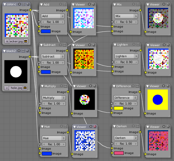
Below are samples of common mix modes and uses, mixing a color or checker with a mask.
Some explanation of the mixing methods above might help you use the Mix node effectively:
- Add - adding blue to blue keeps it blue, but adding blue to red makes purple. White already has a full amount of blue, so it stays white. Use this to shift a color of an image. Adding a blue tinge makes the image feel colder.
- Subtract: Taking Blue away from white leaves Red and Green, which combined make Yellow (and you never thought you'd need a color wheel again, eh?). Taking Blue away from Purple leaves Red. Use this to de-saturate an image. Taking away yellow makes an image bluer and more depressing.
- Multiply: Black (0.00) times anything leaves black. Anything times White (1.00) is itself. Use this to mask out garbage, or to colorize a black-and-white image.
- Hue: Shows you how much of a color is in an image, ignoring all colors except what is selected: makes a monochrome picture (style 'Black & Hue').
- Mix: Combines the two images, averaging the two.
- Lighten: Like bleach, makes your whites whiter. Use with a mask to lighten up a little.
- Difference: Kinda cute in that it takes out a color. The color needed to turn Yellow into White is Blue. Use this to compare two verrry similar images to see what had been done to one to make it the other; sorta like a change log for images. You can use this to see a watermark you have placed in an image for theft detection.
- Darken, with the colors set here, is like looking at the world through rose-colored glasses (sorry, I just couldn't resist).
Contrast Enhancement using Mix
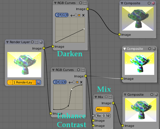
Here is a small map showing the effects of two other common uses for the RGB Curve: Darken and Contrast Enhancement. You can see the effect each curve has independently, and the combined effect when they are mixed equally.
As you can hopefully see, our original magic monkey was overexposed by too much light. To cure an overexposure, you must both darken the image and enhance the contrast. Other paint programs usually provide a slider type of control, but Blender, ah the fantastic Blender, provides a user-definable curve to provide precise control.
In the top RGB curve, Darken, only the right side of the curve was lowered; thus, any X input along the bottom results in a geometrically less Y output. The Enhance Contrast RGB 'S' curve scales the output such that middle values of X change dramatically; namely, the middle brightness scale is expanded, and thus whiter whites and blacker blacks are output. To make this curve, simply click on the curve and a new control point is added. Drag the point around to bend the curve as you wish. The Mix node combines these two effects equally, and Suzanne feels much better. And NOBODY wants a cranky monkey on their hands.
Using Mix to Watermark images
In the old days, a pattern was pressed into the paper mush as it dried, creating a mark that identified who made the paper and where it came from. The mark was barely perceptible except in just the right light. Probably the first form of subliminal advertising. Nowadays, people watermark their images to identify them as personal intellectual property, for subliminal advertising of the author or hosting service, or simply to track their image's proliferation throughout the web. Blender provides a complete set of tools for you to both encode your watermark and to tell if an image has your watermark.
Encoding Your Watermark in an Image
First, construct your own personal watermark. You can use your name, a word, or a shape or image not easily replicated. While neutral gray works best using the encoding method suggested, you are free to use other colors or patterns. It can be a single pixel or a whole gradient; it's up to you. In the example below, we are encoding the watermark in a specific location in the image using the Translate node; this helps later because we only have to look in a specific location for the mark. We then use the RGB to BW node to convert the image to numbers that the Map Value node can use to make the image subliminal. In this case, it reduces the mark to one-tenth of its original intensity. The Add node adds the corresponding pixels, make the ones containing the mark ever-so-slightly brighter.
Of course, if you want people to notice your mark, don't scale it so much, or make it a contrasting color. There are also many other ways, using other mix settings and fancier rigs. Feel free to experiment!
Additional uses
You can also use this technique, using settings that result in visible effects, in title sequences to make the words appear to be cast on the water's surface, or as a special effect to make words appear on the possessed girl's forearm. yuk.
|
Decoding an Image for your Watermark
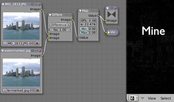
When you see an image that you think might be yours, use the node map below to compare it to your stock image (pre-watermarked original). In this map, the Mix node is set to Difference, and the Map Value node amplifies any difference. The result is routed to a viewer, and you can see how the original mark stands out, clear as a bell:
Various image compression algorithms lose some of the original; the difference shows as noise. Experiment with different compression settings and marks to see which works best for you by having the encoding map in one scene, and the decoding map in another. Use them while changing Blender's image format settings, reloading the watermarked image after saving, to get an acceptable result. In the example above, the mark was clearly visible all the way up to JPEG compression of 50%.
Using Dodge and Burn (History Lesson)
Use the dodge and burn mix methods in combination with a mask to affect only certain areas of the image. In the old darkroom days, when, yes, I actually spent hours in a small stinky room bathed in soft red light, I used a circle cutout taped to a straw to dodge areas of the photo as the exposure was made, casting a shadow on the plate and thus limiting the light to a certain area.
To do the opposite, I would burn in an image by holding a mask over the image. The mask had a hole in it, letting light through and thus 'burning' in the image onto the paper. The same equivalent can be used here by mixing an alpha mask image with your image using a dodge mixer to lighten an area of your photo. Remember that black is zero (no) effect, and white is one (full) effect. And by the way, ya grew to like the smell of the fixer, and with a little soft music in the background and the sound of the running water, it was very relaxing. I kinda miss those dayz.
Hue Saturation Node
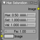
As an alternative to RGB editing, color can be thought of as a mix of Hues, namely a normalized value along the visible spectrum from infra-red to ultraviolet (the rainbow, remember "Roy G. Biv"). The amount of the color added depends on the saturation of that color; the higher the saturation, the more of that pigment is added. Use the saturation slider of this node to "bring out" the colors of a washed-out image.
This node takes an input image and runs the color of the image (and the light it reflects and radiates) 'up' through a factor (0.0-1.0) and applies a saturation of color effect of a hue to the image:
- Hue:
- The Hue slider specifies how much to shift the hue of the image. Hue 0.5 (in the middle) does not shift the hue or affect the color of the image. As Hue shifts left, the colors shift as more cyan is added; a blue image goes bluer, then greener, then yellow. A red image goes violet, then purple, blue, and finally teal. Shifting right (increasing Hue from 0.5 to 1.0) introduces reds and greens. A blue image goes purple, plum, red, orange, and then yellow. A red image goes golden, olive, green, and cyan.
- Sat:
- Saturation affect the amount of pigment in the image. A saturation of 0 actually removes hues from the color, resulting in a black-and-white grayscale image. A saturation of 1.0 blends in the hue, and 2.0 doubles the amount of pigment and brings out the colors.
- Val:
- Value affects the overall amount of the color in the image. Increasing values make an image lighter; decreaing values shift an image darker.
- Fac:
- Factor determines how much this node affects the image. A factor of 0 means that the input image is not affected by the Hue and Saturation settings. A factor of 1 means they rule, with .5 being a mix.
Hue/Saturation tips
Some things to keep in mind that might help you use this node better:
- Hues are vice versa.
- A blue image, with a Hue setting at either end of the spectrum (0 or 1), is output as yellow (recall that white, minus blue, equals yellow). A yellow image, with a Hue setting at 0 or 1, is blue.
- Hue and Saturation work together.
- So, a Hue of .5 keeps the blues the same shade of blue, but the saturation slider can deepen or lighten the intensity of that color.
- Gray & White are neutral hues.
- A gray image, where the RGB values are equal, has no hue. Therefore, this node can only affect it with the Val slider. This applies for all shades of gray, from black to white; wherever the values are equal.
- Changing the effect over time.
- The Hue and Saturation values are set in the node by the slider, but you can feed a Time input into the Factor to bring up (or down) the effect change over time.
Tinge
This HSV node simply shifts hues that are already there. To colorize a gray image, or to ADD color to an image, use a mix node to add in a static color from an RGB input node with your image.
|
HSV Example
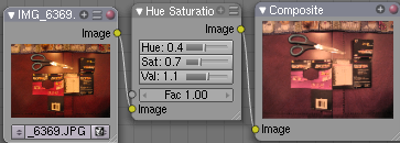
Here, the image taken by a cheap digital camera in poor lighting at night using a flash (can we do it any worse, eh?) is adjusted by decreasing the Hue (decreasing reds and revealing more blues and greens), decreasing Saturation (common in digital cameras, and evens out contrast) and increasing Value (making it all lighter).
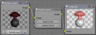
Bright/Contrast
- Bright
- A multiplier-type factor by which to increase the overall brightness of the image. Use a negative number to darken an image.
- Contrast
- A scaling type factor by which to make brighter pixels brighter but keeping the darker pixels dark. Higher values make details stand out. Use a negative number to decrease the overall contrast in the image.
Notes
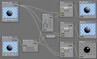
It is possible that this node will put out a value set that has values beyond normal range, i.e. values > 1 or < 0. If you will be using the output to mix with other images in the normal range, you should clamp the values using the Map Value node (with the Min and Max enabled), or put through a ColorRamp node (with all normal defaults).
Either of these nodes will scale the values back to normal range. In the example image, we want to amp up the specular pass. The bottom thread shows what happens if we do not clamp the values; the specular pass has valued much less than 1 in the dark areas; when added to the medium gray, it makes black. Passing the brightened image through either the Map Value or the ColorRamp produces the desired effect.
Gamma
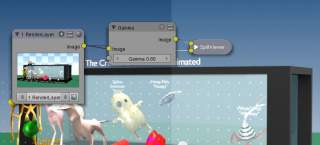
A reason for applying gamma correction to the final render is to correct lighting issues. Lighting issues that can be corrected by a gamma correction node are light attenuation with distance, light falloff at terminators, and light and shadow superpositions. Simply think about the renderer as a virtual camera. By applying a gamma correction to your render, you are just replicating what digital camera do with photos. Digital cameras gamma correct their photos, so you do the same thing. The gamma correction is, indeed, 0.45, not 2.2.
But reverse gamma correction on textures and colors have another very important consequence when you are using rendering techniques such as radiosity or GI. When doing the GI calculations, all textures and colors are taken to mean reflectance. If you do not reverse gamma correct your textures and colors, then the GI render will look way too bright because the reflected colors are all way too high and thus a lot more light is bouncing around than it should.
Gamma correction in Blender enters in a few places. The first is in this section with the nodes, both this node and the Tonemap node, and the second is in calculating Radiosity. In the noodle to the left, the split viewer shows the before and after effect of applying a gamma correction.
Invert
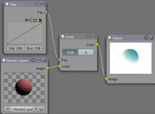
This handy node inverts the colors in the input image, producing a negative.
Options
- Factor
- Controls the amount of influence the node exerts on the output image
- Color
- The input image. In this case, a red sphere on a black transparent background
- RGB
- Invert the colors from white. In this example, red inverted is cyan (teal).
- A
- Invert the alpha (transparency) channel as well. Handy for masking.
AlphaOver Node
Use this node to layer images on top of one another. This node takes two images as input, combines them by a factor, and outputs the image. Connect the Background image to the top input, and the foreground image to the lower input. Where the foreground image pixels have an alpha greater than 0 (namely, have some visibility), the background image will be overlaid.
Use the Factor slider to 'merge' the two pictures. A factor less than 1.00 will make the foreground more transparent, allowing the background to bleed through.
Examples
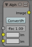
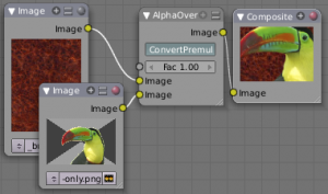
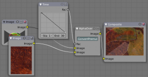
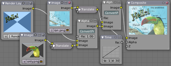
In this example, an image of a Toucan is superimposed over a wooden background. Use the PreMultiply button when the foreground image and background images have a combined Alpha that is greater than 1.00; otherwise you will see an unwanted halo effect. The resulting image is a composite of the two source images.
In this example, we use the Factor control to make a sheer cloth or onion-skin effect. You can animate this effect, allowing the observer to 'see-through' walls (or any foreground object) by hooking up a Time node to feed the Factor socket as shown below. In this example, over the course of 30 frames, the Time node makes the AlphaOver node produce a picture that starts with the background wood image, and slowly bleeds through the Toucan. This example shows frame 11 just as the Toucan starts to be revealed.
AlphaOver does not work on the colors of an image, and will not output any image when one of the sockets is unconnnected.
Strange Halos or Outlines
To clarify the premultiplied-alpha button: An alpha channel has a value of between 0 and 1. When you make an image transparent (to composite it over another one), you are really multiplying the RGB pixel values by the alpha values (making the image transparent (0) where the alpha is black (0), and opaque (1) where it is white (1)).
So, to composite image A over image B, you get the alpha of image A and multiply it by image A, thus making the image part of A opaque and the rest transparent. You then inverse the alphas of A and multiply image B by it, thus making image B transparent where A is opaque and vice versa. You then add the resultant images and get the final composite.
A pre-multiplied alpha is when the image (RGB) pixels are already multiplied by the alpha channel, therefore the above compositing op doesn't work too well, and you have to hit 'convert pre-mult'. This is only an issue in semi transparent area, and edges usually. The issue normally occurs in Nodes when you have combined, with alpha, two images, and then wish to combine that image with yet another image. The previously combined image was previously multiplied (pre-mult) and needs to be converted as such (hence, Convert PreMul).
If you don't pay attention and multiply twice, you will get a white or clear halo around your image where they meet, since your alpha value is being squared or cubed. It also depends on whether or not you have rendered your image as a pre-mult, or straight RGBA image.
Z-Combine Node
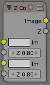
The Z-Combine node takes two images and two Z-value sets as input. It overlays the images using the provided Z values to detect which parts of one image are in front of the other. If both Z values are equal, it uses the top image. It puts out the combined image, with the combined Z-depth map, allowing you to thread multiple Z-combines together.
Z-Combine chooses whichever Z-value is less when deciding which image pixel to use. Normally, objects are in front of the camera and have a positive Z value. If one Z-value is negative, and the other positive, Z-Combine will use the image corresponding to the negative value. You can think of a negative Z value as being behind the camera. When choosing between two negative Z-values, Z-Combine will use whichever is more negative.
Alpha values carry over from the input images. Not only is the image pixel chosen, but also its alpha channel value. So, if a pixel is partially or totally transparent, the result of the Z-Combine will also be partially transparent; in which case the background image will show through the foreground (chosen) pixel. Where there are sharp edges or contrast, the alpha map will automatically be anti-aliased to smooth out any artifacts.
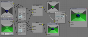
However, you can obtain this by making an AlphaOver of two Z-Combine, one normal, the other having inverted (reversed?) Z-values as inputs, obtained using for each of them a MapValue node with a Size field set to -1.0:
Examples
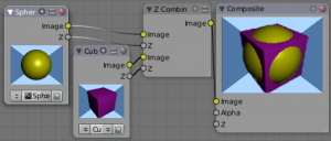
In the example to the right, render output from two scenes are mixed using the Z-Offset node, one from a sphere of size 1.30, and the other a cube of size 1.00. The sphere and square are located at the same place. The cube is tipped forward, so the corner in the center is closer to the camera than the sphere surface; so Z-Offset chooses to use the cube's pixels. But the sphere is slightly larger (a size of 1.30 versus 1.00), so it does not fit totally 'inside' the cube. At some point, as the cube's sides recede back away from the camera, the sphere's sides are closer. When this happens, Z-offset uses the sphere's pixels to form the resulting picture.
This node can be used to combine a foreground with a background matte painting. Walt Disney pioneered the use of multi-plane mattes, where three or four partial mattes were painted on glass and placed on the left and right at different Z positions; mininal camera moves to the right created the illusion of depth as Bambi moved through the forest.
Valid Input
Z Input Sockets do not accept fixed values; they must get a vector set (see Map Value node). Image Input Sockets will not accept a color, since it does not have UV coordinates.
|
You can use Z-Combine to merge two images as well, using the Z-values put out by two renderlayers. Using the Z-values from the sphere and cube scenes above, but threading different images, yields the example to the right.
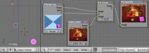
In this noodle (you may click the little expand-o-matic icon in the bottom right to view it to full size), we mix a render scene with a flat image. In the side view of the scene, the purple cube is 10 units away from camera, and the gray ball is 20. The 3D cursor is about 15 units away from camera. We Z-in the image at a location of 15, thus inserting it in-between the cube and the ball. The resulting image appears to have the cube on the table.
Invisible Man Effect
If you choose a foreground image which has a higher Alpha than the background, and then mix the Z-combine with a slightly magnified background, the outline of the transparent area will distort the background, enough to make it look like you are seeing part of the background through an invisible yet Fresnel-lens object.
|
Color Balance
The Color Balance node can adjust the color and values of an image using two different correction formulas.
- The Lift, Gammma, Gain formula uses Lift, Gamma, and Gain calculations to adjust an image.Lift increases the value of dark colors, Gamma will adjust midtones, and Gain adjusts highlights.
- The Offset, Power, Slope formula uses Offset, Power, and Slope
out = (i*s+o)^p,
- where
- out = the color graded pixel code value
- i = the input pixel code value (0=black, 1=white)
- s = slope (any number 0 or greater, nominal value is 1.0)
- o = offset (any number, nominal value is 0)
- p = power (any number greater than 0, nominal value is 1.0)
- Factor
- Controls the amount of influence the node exerts on the output image
Hue Correct
The Hue Correct node is able to adjust the Hue, Saturation, and Value of an image, with an input curve.
By default, the curve is a straight line, meaning there is no change. The spectrum allows you to raise or lower HSV levels for each range of pixel colors. To change a H, S, or V level, move the curve points up or down. Pixels with hue values each point in the horizontal position of the graph will be changed depending on the shape of the curve.
Tone Map
Tone mapping is a technique used in image processing and computer graphics to map one set of colors to another in order to approximate the appearance of high dynamic range images in a medium that has a more limited dynamic range.
Essentially, tone mapping addresses the problem of strong contrast reduction from the scene values (radiance) to the displayable range while preserving the image details and color appearance important to appreciate the original scene content.
The Tone Map node has two methods of calculation:
- Rh Simple
- Key
- The value the average luminance is mapped to.
- Offset
- Normally always 1, but can be used as an extra control to alter the brightness curve
- Gamma
- If not used, set to 1
- R/D Photoreceptor
- Intensity
- If less than zero, darkens image; otherwise, makes it brighter
- Contrast
- Set to 0 to use estimate from input image
- Adaptation
- If 0, global; if 1, based on pixel intensity
- Color Correction
- If 0, same for all channels; if 1, each independent
