Doc:2.6/Manual/Composite Nodes/Types/Filter
Page status (reviewing guidelines)
Copy
This page is a copy of the same page in 2.4 manual, need to be updated
|
Composite Filter Nodes
Filters process the pixels of an image to highlight additional details or perform some sort of post-processing effect on the image.
Filter Node
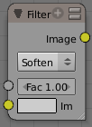
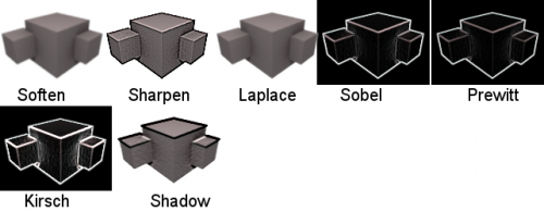
The Filter node implements various common image enhancement filters. The supported filters are, if not obvious, named after the mathematical genius who came up with them:
- Soften
- Slightly blurs the image.
- Sharpen
- Increases the contrast, especially at edges
- Laplace
- Softens around edges
- Sobel
- Creates a negative image that highlights edges
- Prewitt
- Tries to do Sobel one better.
- Kirsch
- Improves on the work done by those other two flunkies, giving a better blending as you approach an edge.
- Shadow
- Performs a relief emboss/bumpmap effect, darkening outside edges.
The Soften, Laplace, Sobel, Prewitt and Kirsch all perform edge-detection (in slightly different ways) based on vector calculus and set theory equations that would fill six blackboards with gobbledy gook. Recommended reading for insomniacs.
Blur Node
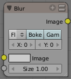
The Blur node blurs an image, using one of seven blur modes (set using the upper-left popup button), and a radius defined by the X and Y number buttons. By default these are set to zero, so to enable the node you must set one or both to a value greater then 0. You can optionally connect a value image to the Size input node, to control the blur radius with a mask. The values must be mapped between 0-1 for best effect, as they will be multiplied with the X and Y number button values.
Options
The X and Y values are the number of pixels over which to spread the blur effect.
The Bokeh button (only visible as Bok or Bo on some screen setups) will force the blur node to use a circular blur filter. This gives higher quality results, but is slower then using a normal filter. The Gam button (for "gamma") makes the Blur node gamma-correct the image before blurring it.
The difference between them is how they handle sharp edges and smooth gradients and preserve the highs and the lows. In particular (and you may have to closely examine the full-resolution picture to see this):
- Flat just blurs everything uniformly
- Tent preserves the high and the lows better making a linear falloff
- Quadratic and CatRom keep sharp-contrast edges crisp
- Cubic and Mitch preserve the highs but give almost a out-of-focus blur while smoothing sharp edges
Directional Blur Node
Blurs an image in a specified direction and magnitude. Can be used to fake motion blur.
Options
- Iterations
- Controls how may times the image is duplicated to create the blur effect. Higher values give smoother results.
- Wrap
- Wraps the image on the X and Y axis to fill in areas that become transparent from the blur effect.
- Center
- Sets the position where the blur center is. This makes a difference if the angle, spin, and/or zoom are used.
- Distance
- How large the blur effect is.
- Angle
- Image is blurred at this angle from the center
- Spin
- Rotates the image each iteration to create a spin effect, from the center point.
- Zoom
- Scales the image each iteration, creating the effect of a zoom.
Example
An example blend file, in fact the one used to create the image above, is available here. The .blend file takes one image from the RenderLayer "Blurs" and blurs it while offsetting it (Translate) and then combining it (AlphaOver) to build up the progressive sequence of blurs. Play with the Value and Multiply nodes to change the amount of blurring that each algorithm does.
Bilateral Blur Node
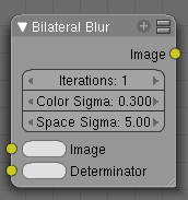
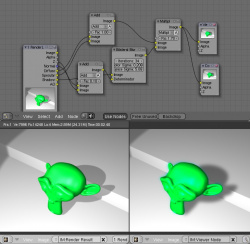
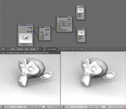
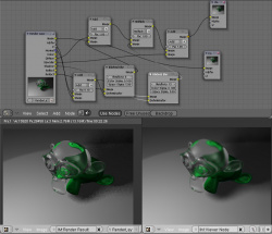
The bilateral blur node performs a high quality adaptive blur on the source image. It can be used for various purposes like:
- smoothing results from blenders raytraced ambient occlusion
- smoothing results from various unbiased renderers,
- to fake some performance-heavy processes, like blurry refractions/reflections, soft shadows,
- to make non-photorealistic compositing effects.
Inputs
Bilateral blur has 2 inputs:
- Image, for the image to be blurred.
- Determinator, which is non-obligatory, and is used only if connected.
if only 1st input is connected, the node blurs the image depending on the edges present in the source image. If the Determinator is connected, it serves as the source for defining edges/borders for the blur in the image. This has great advantage in case the source image is too noisy, but normals in combination with zbuffer can still define exact borders/edges of objects.
Options
- Iterations
- Defines how many times the filter should perform the operation on the image. It practically defines the radius of blur.
- Color Sigma
- Defines the threshold for which color differences in the image should be taken as edges.
- Space sigma
- A fine-tuning variable for blur radius.
Examples
Vector (Motion) Blur Node
Motion blur is the effect of objects moving so fast they blur. Because CG animations work by rendering individual frames, they have no real knowledge of what was where in the last frame, and where it is now.
In Blender, there are two ways to produce motion blur. The first method (which produces the most correct results) works by rendering a single frame up to 16 times with slight time offsets, then accumlating these images together; this is called Motion Blur and is activated on the Render panel. The second (and much faster) method is the Compositor node Vector Blur.
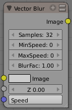
To use, connect the appropriate passes from a Render Result node.
Note
Make sure to enable the Speed (called Vec) pass in the Render Layers panel for the render layer you wish to perform motion blur on.
|
Maximum Speed: Because of the way vector blur works, it can produce streaks, lines and other artifacts. These mostly come from pixels moving too fast; to combat these problems, the filter has minimum and maximum speed settings, which can be used to limit which pixels get blurred (e.g. if a pixel is moving really, really fast but you have maximum speed set to a moderate amount, it won't get blurred).
Minimum Speed: Especially when the camera itself moves, the mask created by the vectorblur node can become the entire image. A very simple solution is to introduce a small threshold for moving pixels, which can efficiently separate the hardly-moving pixels from the moving ones, and thus create nice looking masks. You can find this new option as 'min speed'. This minimum speed is in pixel units. A value of just 3 will already clearly separate the background from foreground.
Hint
You can make vector blur results a little smoother by passing the Speed pass through a blur node (but note that this can make strange results, so it's only really appropriate for still images with lots of motion blur).
|
Examples
An in-depth look at how to use the Vector Blur node can be found here.
As far as we know, this node represents a new approach to calculating motion blur. Use vector blur in compositing with confidence instead of motion blur. In face, when compositing images, it is necessary to use vector blur since there isn't "real" motion. In this example blend file, you will find a rigged hand reaching down to pick up a ball. Based on how the hand is moving (those vectors), the image is blurred in that direction. The fingers closest to the camera (the least Z value) are blurred more, and those farther away (the forearm) is blurred the least.
Known Bugs
Does not work when reading from a multilayer OpenEXR sequence set
Dilate/Erode Node
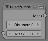
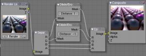
This node blurs individual color channels. The color channel (or a black and white image) is connected to the Mask input socket, and the Distance is set manually (by clicking on the arrows or the value) or automatically from a value node or a time-and-map-value noodle. A positive value of Distance expands the influence of a pixel on its surrounding pixels, thus blurring that color outward. A negative value erodes its influence, thus increases the constrast of that pixel relative to its surrounding pixels, thus sharpening it relative to surrounding pixels of the same color.
Example
In the above example image, we wanted to take the rather boring array of ball bearings and spruce it up; make it hot, baby. So, we dilated the red and eroded the green, leaving the blue alone. If we had dilated both red and green...(hint: red and green make yellow). The amount of influence is increased by increasing the Distance values. Blend file available here.
Defocus
This single node can be used to emulate depth of field using a postprocessing method. It can also be used to blur the image in other ways, not necessarily based on 'depth' by connecting something other than a Zbuffer. In essence, this node blurs areas of an image based on the input zbuffer map/mask.
Camera Settings
The Defocus node uses the actual camera data in your scene if supplied by a RenderLayer node.
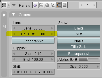
To set the point of focus, the camera now has a Distance parameter, which is shorthand for Depth of Field Distance. Use this camera parameter to set the focal plane of the camera (objects Depth of Field Distance away from the camera are in focus). Set Distance in the main Camera edit panel; the button is right below the Depth of Field.
To make the focal point visible, enable the camera Limits option, the focal point is then visible as a yellow cross along the view direction of the camera.
Node Inputs
The node requires two inputs, an image and a zbuffer, the latter does not need to be an actual zbuffer, but can also be another (grayscale) image used as mask, or a single value input, for instance from a time node, to vary the effect over time.
Node Setting
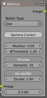
The settings for this node are:
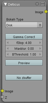
- Bokeh Type menu
- Here you set the number of iris blades of the virtual camera's diaphragm. It can be set to emulate a perfect circle (Disk) or it can be set to have 3 (Triangle), 4 (Square), 5 (Pentagon), 6 (Hexagon), 7 (Heptagon) or 8 blades (Octagon). The reason it does not go any higher than 8 is that from that point on the result tends to be indistinguishable from a Disk shape anyway.
- Rotate
- This button is not visible if the Bokeh Type is set to Disk. It can be used to add an additional rotation offset to the Bokeh shape. The value is the angle in degrees.
- Gamma Correct
- Exactly the same as the Gamma option in Blender's general Blur node (see Blur Node). It can be useful to further brighten out of focus parts in the image, accentuating the Bokeh effect.
- fStop
- This is the most important parameter to control the amount of focal blur: it simulates the aperture f of a real lens(' iris) - without modifying the luminosity of the picture, however! As in a real camera, the smaller this number is, the more-open the lens iris is, and the shallower the depth-of-field will be. The default value 128 is assumed to be infinity: everything is in perfect focus. Half the value will double the amount of blur. This button is not available if No zbuffer is enabled.
- Maxblur
- Use this to limit the amount of blur of the most out of focus parts of the image. The value is the maximum blur radius allowed. This can be useful since the actual blur process can sometimes be very slow. (The more blur, the slower it gets.) So, setting this value can help bring down processing times, like for instance when the world background is visible, which in general tends to be the point of maximum blur (not always true, objects very close to the lens might be blurred even more). The default value of 0 means there is no limit to the maximum blur amount.
- BThreshold
- The defocus node is not perfect: some artifacts may occur. One such example is in-focus objects against a blurred background, which have a tendency to bleed into the edges of the sharp object. The worst-case scenario is an object in-focus against the very distant world background: the differences in distance are very large and the result can look quite bad. The node tries to prevent this from occurring by testing that the blur difference between pixels is not too large, the value set here controls how large that blur difference may be to consider it 'safe.' This is all probably quite confusing, and fortunately, in general, there is no need to change the default setting of 1. Only try changing it if you experience problems around any in-focus object.
- Preview
- As already mentioned, processing can take a long time. So to help make editing parameters somewhat 'interactive', there is a preview mode which you can enable with this button. Preview mode will render the result using a limited amount of (quasi)random samples, which is a lot faster than the 'perfect' mode used otherwise. The sampling mode also tends to produce grainy, noisy pictures (though the more samples you use, the less noisy the result). This option is on by default. Play around with the other parameters until you are happy with the results, and only then disable the preview mode for the final render.
- Samples
- Only visible when Preview is set. Sets the amount of samples to use to sample the image. The higher, the smoother the image, but also the longer the processing time. For preview, the default of 16 samples should be sufficient and is also the fastest.
- No zbuffer
- Sometimes you might want to have more control to blur the image. For instance, you may want to only blur one object while leaving everything else alone (or the other way around), or you want to blur the whole image uniformly all at once. The node therefore allows you to use something other than an actual zbuffer as the Z input. For instance, you could connect an image node and use a grayscale image where the color designates how much to blur the image at that point, where white is maximum blur and black is no blur. Or, you could use a Time node to uniformly blur the image, where the time value controls the maximum blur for that frame. It may also be used to obtain a possibly slightly-better DoF blur, by using a fake depth shaded image instead of a zbuffer. (A typical method to create the fake depth shaded image is by using a linear blend texture for all objects in the scene or by using the 'fog/mist' fake depth shading method.) This also has the advantage that the fake depth image can have anti-aliasing, which is not possible with a real zbuffer. "No zbuffer" will be enabled automatically whenever you connect a node that is not image based (e.g. time node/value node/etc).
- Zscale
- Only visible when No zbuffer enabled. When No zbuffer is used, the input is used directly to control the blur radius. And since usually the value of a texture is only in the numeric range 0.0 to 1.0, its range is too narrow to control the blur properly. This parameter can be used to expand the range of the input (or for that matter, narrow it as well, by setting it to a value less than one). So for No zbuffer, this parameter therefore then becomes the main blur control (similar to fStop when you do use a zbuffer).
Examples
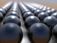
In this blend file example, the ball array image is blurred as if it was taken by a camera with a f-stop of 2.8 resulting in a farily narrow depth of field centered on 7.5 blender units from the camera. As the balls receed into the distance, they get blurrier.
Hints
- Preview
- In general, use preview mode, change parameters to your liking, only then disable preview mode for the final render. This node is compute intensive, so watch your console window, and it will give you status as it computes each render scan line.
- Edge Artifacts
- For minimum artifacts, try to setup your scene such that differences in distances between two objects that may visibly overlap at some point are not too large.
- "Focus Pull"
- Keep in mind that this is not 'real' DoF, only a post-processing simulation. Some things cannot be done which would be no problem for real DoF at all. A typical example is a scene with some object very close to the camera, and the camera focusing on some point far behind it. In the real world, using shallow depth of field, it is not impossible for nearby objects to become completely invisible, in effect allowing the camera to see 'behind' it. Hollywood cinematographers use this visual characteristic to good effect to achieve the popular "focus pull" effect, where the focus shifts from a nearby to a distant object, such that the "other" object all but disappears. Well, this is simply not possible to do with the current post-processing method in a single pass. If you really want to achieve this effect, quite satisfactorily, here's how:
- Split up your scene into "nearby" and "far" objects, and render them in two passes.
- Now, combine the two the two results, each with their own "defocus" nodes driven by the same Time node, but with one of them inverted. (e.g. using a "Map Value" node with a Size of -1.) As the defocus of one increases, the defocus on the other decreases at the same rate, creating a smooth transition.
- Aliasing at Low f-Stop Values
- At very low values, less than 5, the node will start to remove any oversampling and bring the objects at DoFDist very sharply into focus. If the object is against a constrasting background, this may lead to visible stairstepping (aliasing) which OSA is designed to avoid. If you run into this problem:
- Do your own OSA by rendering at twice the intended size and then scaling down, so that adjacent pixels are blurred togther
- Use the blur node with a setting of 2 for x and y
- Set DoFDist off by a little, so that the object in focus is blurred by the tiniest bit.
- Use a higher f-Stop, which will start the blur, and then use the Z socket to a Map Value to a Blur node to enhance the blur effect.
- Rearrange the objects in your scene to use a lower-contrast background
- No ZBuffer
- A final word of warning, since there is no way to detect if an actual zbuffer is connected to the node, be VERY careful with the "No ZBuffer" switch. If the Zscale value happens to be large, and you forget to set it back to some low value, the values may suddenly be interpreted as huge blur-radius values that will cause processing times to explode.
