Doc:2.6/Manual/Composite Nodes/Types/Input
Page status (reviewing guidelines)
Copy This page is a copy of the same page in 2.4 manual, need to be updated Text
This page contains some direct how-tos that should be in the example and tutorial section
|
Composite Input Nodes
Input nodes produce information from some source.
For instance, an input could be:
- taken directly from the active camera in a selected scene,
- from a JPG, PNG, etc. file as a static picture,
- a movie clip (such as an animation sequence or home movie), or
- just a color.
These nodes generate the information that feeds other nodes. As such, they have no input-connectors; only outputs.
Render Layers Node
This node is the starting place to getting a picture of your scene into the compositing node map.
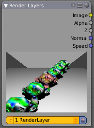
This node inputs an image from a scene within your blend file. Select the scene and the active render layer from the yellow selection list at the bottom of the node. Blender uses the active camera for that scene to create an image of the objects specified in the RenderLayer.
The Image is input into the map, along with the following data:
- Alpha (transparency) mask
Depending on the Renderlayer passes that are enabled, other sockets are available. By default the Z is enabled:
- Z depth map (how far away each pixel is from the camera)
The example shows that two other passes are enabled:
- Normal vector set (how light bounces off the surface)
- Speed vector set (how fast an object is moving from one frame to the next)
Use the re-render button (Small landscape icon - to the right of the Renderlayer name) to re-render the scene and refresh the image and map.
You may recall that a .blend file may contain many scenes. The Renderlayer node can pick up the scene info from any available scene by selecting the scene from the left-hand selector. If that other scene also uses the compositor and/or sequencer, you should note that the scene information taken is the raw information (pre-compositing and pre-sequencing). If you wish to use composited information from another scene, you will have to render that scene to a multilayer OpenEXR frameset as an intermediate file store, and then use the Image input node instead.
Using the Alpha Socket
Using the Alpha output socket is crucial in overlaying images on top of one another and letting a background image "show through" the image in front of it.
In a Blender scene, your objects are floating out there in virtual space. While some objects are in front of one another (Z depth), there is no ultimate background. Your world settings can give you the illusion of a horizon, but it's just that: an illusion. Further, some objects are semi-transparent; this is called having an Alpha value. A semi-transparent object allows light (and any background image) to pass through it to the camera. When you render an image, Blender puts out, in addition to a pretty image, a map of what solid objects actually are there, and where infinity is, and a map of the alpha values for semi-transparent objects. You can see this map by mapping it to a blue screen:
In the little node map above, we have connected the Alpha output socket of the RenderLayer node to a Map Value node (explained later, but basically this node takes a set of values and maps them to something we can use). The Color Ramp node (also explained later in detail) takes each value and maps it to a color that we can see with our eyes. Finally, the output of the Color Ramp is output to a Composite viewer to show you, our dear reader, a picture of the Alpha values. Notice that we have set up the map so that things that are perfectly solid (opaque) are white, and things that are perfectly transparent (or where there is nothing) are blue.
Optional Sockets
For any of the optional sockets to appear on the node, you MUST have the corresponding pass enabled. In order for the output socket on the RenderLayer node to show, that pass must be enabled in the RenderLayer panel in the Buttons window. For example, in order to be able to have the Shadow socket show up on the RenderLayer input node, you must have the "Shad" button enabled in the Buttons window, Scene Render buttons, Renderlayer panel. See the RenderLayer tab (Buttons window, Output frame, Render Layers tab, Passes selector buttons) for Blender to put out the values corresponding to the socket.
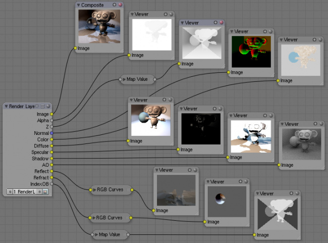
For a simple scene, a monkey and her bouncy ball, the following picture expertly provides a great example of what each pass looks like:
The available sockets are:
- Z: distance away from the camera, in Blender Units
- Normal (Nor): How the color is affected by light coming from the side
- UV: how the image is distorted by the UV mapping
- Speed (Vec): How fast the object is moving, and in what direction
- Color (Col): the RGB values that color the image that you see
- Diffuse: the softening of colors as they diffuse through the materials
- Specular: the degree of shininess added to colors as they shine in the light
- Shadow: shadows cast by objects onto other objects
- AO: how the colors are affected by Ambient Occlusion in the world
- Reflect (Ref): for mirror type objects, the colors they reflect and are thus not part of their basic material
- Refract: how colors are bent by passing through transparent objects
- Radio (Radiosity): colors that are emitted by other objects and cast onto the scene
- IndexOB: a numeric ordinal (index) of each object in the scene, as seen by the camera.
Using the Z value Socket
Using the Z output socket is crucial in producing realistic images, since items farther away are blurrier (but more on that later).
Imagine a camera hovering over an X-Y plane. When looking through the camera at the plane, Y is up/down and X is left/right, just like when you are looking at a graph. The camera is up in the air though, so it has a Z value from the X-Y plane, and, from the perspective of the camera, the plane, in fact all the objects that the camera can see, have a Z value as a distance that they are away from it. In addition to the pretty colors of an image, a RenderLayer input node also generates a Z value map. This map is a whole bunch of numbers that specify how far away each pixel in the image is away from the camera. You can see this map by translating it into colors, or shades of gray:
In the little node map above, we have connected the Z output socket of the RenderLayer node to a Map Value node (explained later). This node takes a set of values and maps them to something we can use. The Color Ramp node (also explained later in detail) takes each value and maps it to a shade of gray that we can see with our eyes. Finally, the output of the colorramp is output to a Composite viewer to show you, our dear reader, a picture of the Z values. Notice that we have set up the Map Value node so that things closer to the camera appear blacker (think: black is 0, less Z means a smaller number) and pixels/items farther away have an increasing Z distance and therefore get whiter. We chose a Size value of 0.05 to see Z values ranging from 0 to 20 (20 is 1/0.05).
Using the Speed Socket
Even though things may be animated in our scene, a single image or frame from the animation does not portray any motion; the image from the frame is simply where things are at that particular time. However, from the Render Layers node, Blender puts out a vector set that says how particular pixels are moving, or will move, to the next frame. You use this socket to create a blurring effect. Find out more by clicking here.
Image node
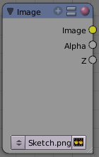
The Image node injects any image format that is supported by Blender. Besides inputting the actual image, this node can also input Alpha and depth (Z) values if the image has them. If the image is a MultiLayer format, all saved render passes are input. Use this node to input:
- A single image from a file (such as a JPG picture)
- Part or all of an animation sequence (such as the 30th to 60th frame)
- Part or all of a movie clip (such as an AVI file)
- the image that is currently in the UV/Image Editor (and possibly being painted)
- an image that was loaded in the UV/Image Editor
To select an image file or generated image from the UV/Image Editor, click on the small arrow selector button to the left of the name and pick an existing image (e.g. loaded in the UV editor or elsewhere) or click on LOAD NEW to select a file from your hard disk via a file-browser. These images can be e.g. previously rendered images, matte paintings, a picture of your cat, whatever. Blender really doesn't care.
If the image is part of a sequence, manually click the Image Type selector to the right of the name, and select Sequence. Additional controls will allow you to define how much of the sequence to pull in (see Animations below). If the file is a video file, these controls will automatically appear.
Image Channels
When the image is loaded, the available channels will be shown as sockets on the node. As a minimum, the Image, Alpha, and Z channels are made available. The picture may or may not have an alpha (transparency) and/or Z (depth) channel, depending on the format. If the image format does not support A and/or Z, default values are supplied (1.0 for A, 0.0 for Z).
- Alpha/Transparency Channel
- If a transparency channel is detected, the Alpha output socket will supply it.
- If it does not have an Alpha channel (e.g. JPG images), Blender will supply one, setting the whole image to completely opaque (an Alpha of 1.00, which will show in a Viewer node as white - if connected to the Image input socket).
- Z/depth Channel
- If a Z (depth) channel is detected, the Z output socket will supply it.
- If it does not have a Z channel (e.g. JPG or PNG images), Blender will supply one, setting the whole image to be at the camera (a depth of 0.00). To view the Z-depth channel, use the Map Value to ColorRamp noodle given above in the Render Layer input node, in the Render Layer input node.
Formats
Blender supports many image formats. Currently only the OpenEXR image format stores RGB (color), A (alpha), and Z (depth) buffer information in a single file, if enabled.
|
Saving/Retrieving Render Passes
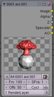
Blender can save the individual Render Layers and specific passes in a MultiLayer file format, which is an extension of the OpenEXR format. In this example, we are reading in frames 50 to 100 of a RenderLayer that were generated some time ago. The passes that were saved were the Image, Alpha, Z, Specular and AO passes.
To create a MultiLayer image set when initially rendering, simply disable Do Composite, set your Format to MultiLayer, enable the Render Layer passes you wish to save over the desired frame range, and Animate. Then, in Blender, enable Compositing Nodes and Do Composite, and use the Image input node to read in the EXR file. When you do, you will see each of the saved passes available as sockets for you to use in your compositing noodle.
Image Size
Size matters - Pay attention to image resolution and color depth when mixing and matching images. Aliasing (rough edges), color flatness, or distorted images can all be traced to mixing inappropriate resolutions and color depths.
The compositor can mix images with any size, and will only perform operations on pixels where images have an overlap. When nodes receive inputs with differently sized Images, these rules apply:
- The first/top Image input socket defines the output size.
- The composite is centered by default, unless a translation has been assigned to a buffer using a Translate node.
So each node in a composite can operate on different sized images, as defined by its inputs. Only the Composite output node has a fixed size, as defined by the Scene buttons (Format Panel - F10). The Viewer node always shows the size from its input, but when not linked (or linked to a value) it shows a small 320x256 pixel image.
Animations
To use image sequences or movies within your composition, press the face or little film strip button located to the right of the selector. As you click, a pop-up will offer you four choices:
- Generated -
- Sequence - a sequence of frames, each frame in a separate file.
- Movie - a sequence of frames packed into a single .avi or .mov file
- Image - a single frame or still image in a file
A Movie or Image can be named anything, but a Sequence must have a digit sequence somewhere in its filename, for example fire0001set.jpg, fire0002set.jpg, fire0003set.jpg and so on. The number indicates the frame.
If a Sequence or Movie is selected, an additional set of controls will appear that allows you to select part or all of the sequence. Use these controls to specify which frames, out of the original sequence, that you want to introduce into the animation you are about to render. You can start at the beginning and only use the beginning, or even pick out a set of frames from the middle of an existing animation.
The Frs number button is the number of frames in the sequence that you want to show. For example, if you want to show 2 seconds of the animation, and are running 30 fps, you would put 60 here.
The SFra number button sets the start frame of the animation; namely, at what point in the animation that you are going to render do you want this sequence to start playing. For example, if you want to introduce this clip ten seconds into the composite output, you would put 300 here (at 30 fps).
The First number button sets the first number in the animated sequence name. For example, if your images were called "credits-0001.png", "credits-0002.png" through "credits-0300.png" and you wanted to start picking up with frame 20, you'd put 20 here.
To have the movie/sequence start over and repeat when it is done, press the Cyclic button. For example, if you were compositing a fan into a room, and the fan animation lasted 30 frames, the animation would start over at frame 31, 61, 91, and so on, continuously looping. As you scrub from frame to frame, to see the actual video frame used for the current frame of animation, press the auto button to the right of the Cyclic button.
Generated Images
Blender features Texture Paint which works in the UV/Image Editor, that allows you to paint on the fly, and the image is kept in memory or saved. If sync lock is enabled (the lock icon in the header), changes are broadcast throughout Blender as soon as you lift the mouse button. One of the places that the image can go is to the Image Input node. The example shows a painting session going on in the right-hand UV/Image Editor window for the painting "Untitled". Create this image via Image->New in the UV/Image Editor. Refer to the texture paint section of the user maual for more info on using Texture Paint.
In the left-hand window, the Image input node was used to select that "Untitled" image. Notice that the Image type icon is blank, indicating that it is pulling in a Generated image. That image is colorized by the noodle, with the result used as a backdrop in the Node Editor Window.
Using this setup and the Generated Image type is like painting and post-processing as you continue painting. Changes to either the painting or the post-pro noodle are dynamic and real-time.
Notes
No Frame Stretching or Compression: If the input animation (avi or frame set) was encoded at a frame rate that is different from your current settings, the resultant animation will appear to run faster or slower. Blender Nodes do not adjust input video frame rates. Use the scale control inside the Video Sequence Editor to stretch or compress video to the desired speed, and input it here. You can incorporate "Slow-Mo" into your video. To do so, ANIMate a video segment at 60 frames per second, and input it via this node, using Render settings that have an animation frame rate of the normal 30 fps; the resulting video will be played at half speed. Do the opposite to mimic Flash running around at hyperspeed.
AVI (Audio Video Interlaced) files are encoded and often compressed using a routine called a Codec. You must have a codec installed on your machine and available to Blender that understands and is able to read the file, in order for Blender to be able to de-code and extract frames from the file. If you get the error message FFMPEG or unsupported video format when trying to load the file, you need to get a Codec that understands the video file. Contact the author of the file and find out how it was encoded. An outside package, such as VirtualDub, might help you track this information down. Codecs are supplied by video device manufacturers, Microsoft, DivX, and Xvid, among others, and can often be downloaded from their web sites for free.
Splicing Video Sequences using Nodes
The above animation controls, coupled with a little mixing, is all you need to splice video sequences together. There are many kinds of splices:
- Cut Splice - literally the ends of the footage are just stuck together
- Fade In - The scene fades in, usually from black
- Fade Out - The scene fades out, usually to black
- Mix - Toward the end of one scene, the images from the next scene meld in as the first scene fades
- Winking and Blinking - fading one cut out while the other fades in, partially or totally through black
- Bumps and Wipes - one cut bumps the other one out of frame, or wipes over it (like from the top left corner down)
Cut Splicing using Nodes
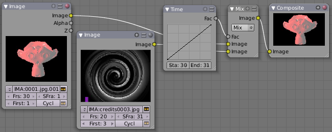
In the example noodle below, we have two pieces of footage that we want to cut splice together.
- Magic Monkey - named 0001.png through 0030.png
- Credits - named credits0001.png through credits0030.png
The editor has reviewed the Credits and thought the first two frames could be thrown away (onto the cutting room floor, as they say) along with the last 8, leaving 20 frames from the total shot. Not shown in this image, but crucial, is that in the Output panel, we set our render output filename to "Monkey-Credits-", and our Animation start and end frames to 1 and 50 (30 from the Monkey, 20 from the credits). Notice the Time node; it tells the Mix node to use the top image until frame 30, and then, at frame 31, changes the Mix factor to 1, which means to use the bottom set of images.
Upon pressing the ANIM button, Blender will composite the animation. If you specified an image format for output, for example, PNG, Blender will create 50 files, named "Monkey-Credits-0001.png" through "Monkey-Credits-0050.png". If you specified a movie format as output, such as AVI-JPEG, then Blender will create only one file, "Monkey-Credits-.avi", containing all 50 frames.
Use cut scenes for rapid-fire transition, conveying a sense of energy and excitement, and to pack in a lot of action in a short time. Try to avoid cutting from a dark scene to a light one, because it's hard on the eyes. It is very emotionally contrasting, and sometimes humorous and ironic, to cut from a very active actor in one scene to a very still actor in another scene, a la old Road Runner and Coyote scenes.
Fade Splicing using Nodes
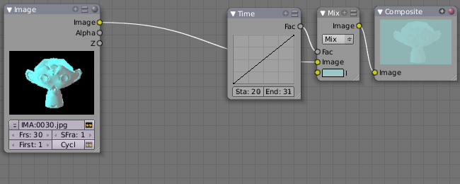
In the previous topic, we saw how to cut from one sequence to another. To fade in or out, we simply replace one set of images with a flat color, and expand the Time frame for the splice. In the image below, beginning at frame 20, we start fading out to cyan:
Cyan was chosen because that is the color of the Monkey at that time, but you can just as easily choose any color. The image below shows frame 30, when we have almost faded completely.
To fade in, change the Mix node and plug the image sequence into the bottom socket, and specify a flat color for the top socket.
Mix Splice using Nodes
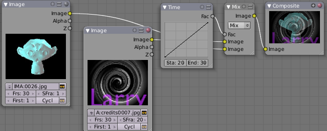
To mix, or crossover, from one scene to the next, start feeding the second scene in while the first is mixing out. The noodle below shows frame 25 of a mix crossover special effect to transition from one scene to the next, beginning at frame 20 with the transition completed by frame 30. Action continues in the first scene as it fades out and is mixed with action that starts in the second scene.
Use this effect to convey similarities between the two scenes. For example, Scene 1 is the robber walking down the street, ending with the camera focusing in on his feet. Scene 2 is a cop walking down the street after him, starting with his feet and working its way up to reveal that the cop is following the robber.
Wink Splice using Nodes
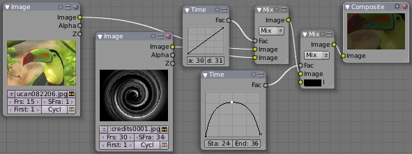
A Wink is just like blinking your eyes; one scene fades to black and the other fades in. To use Blender to get this effect, build on the Cut and Fade splices discussed above to yield:
In the above example, showing frame 27, we have adjusted some parameters to show you the power of Blender and how to use its Nodes to achieve just the blended crossover effect you desire:
- Postfeed: Even though there were only 15 frames of animation in the Toucan strip, the cutover (top Time node) does not occur until frame 30. Blender continues to put out the last frame of an animation, automatically extending it for you, for frames out of the strip's range.
- Prefeed: Even though the swirl does not start playing until frame 34, Blender supplies the first frame of it for Frames 31 through 33. In fact, it supplies this image all the way back to frame 1.
- Partial Fade: Notice the second 'wink' Time node. Like a real wink, it does not totally fade to black; only about 75%. When transitioning between scenes where you want some visual carryover, use this effect because there is not a break in perceptual sequence.
Multiple Feeds
The above examples call out two feeds, but by replicating the Input, Time and Mix nodes, you can have multiple feeds at any one time; just set the Time node to tell the Mixer when to cut over to using it.
|
Texture Node
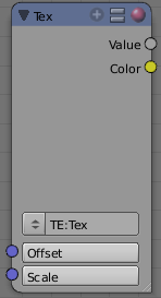
The Texture node makes 3D textures available to the compositor.
The Texture node makes 3D textures available to the compositor. A texture, from the list of textures available in the current blend file, is selected and introduced through the value and/or color socket.
Note
Please read up on the Blender Library system for help on importing and linking to textures in other blender files.
|
Note
You cannot edit the textures themselves in the node window. To use this node, create and edit the texture in the normal texture buttons, then select the texture from the menu button on the node.
|
You can change the Offset and a Scale (which is called Offs XYZ and Size XYZ in the Materials Texture Map Input panel) for the texture by clicking on the label and setting the sliders, thus affecting how the texture is applied to the image. For animation, note that this is a vector input socket, because the XYZ values are needed.
Texture nodes can output a straight black-and-white Value image (don't mistake this for alpha) and an image (Color).
Example
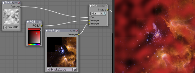
In the example above, we want to simulate some red plasma gas out there in space. So, we fog up an image taken from the Hubble telecscope of Orion and take the ever-so-useful Cloud texture and use it to mix in red with the image.
Value node
The Value node has no inputs; it just outputs a numerical value (floating point spanning 0.00 to 1.00) currently entered in the NumButton displayed in its controls selection.
Use this node to supply a constant, fixed value to other nodes' value or factor input sockets.
RGB node
The RGB node has no inputs. It just outputs the Color currently selected in its controls section; a sample of it is shown in the top box. In the example to the right, a gray color with a tinge of red is slected.
To change the brightness and saturation of the color, LMB ![]() click anywhere within the square gradient. The current saturation is shown as a little circle within the gradient. To change the color itself, click anwhere along the rainbow Color Ramp.
click anywhere within the square gradient. The current saturation is shown as a little circle within the gradient. To change the color itself, click anwhere along the rainbow Color Ramp.
Example
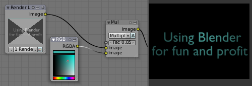
In this example, our corporate color is teal, but the bozo who made the presentation forgot. So, we multiply his lame black and white image with our corporate color to save him from embarassment in front of the boss when he gives his boring presentation.
Time node
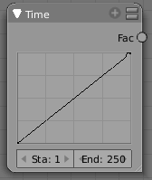
The Time node generates a factor value (from 0.00 to 1.00) (that changes according to the curve drawn) as time progresses through your movie (frames).
The Start and End NumButtons specify the range of time the values should be output along, and this range becomes the X-axis of the graph. The curve defines the Y-value and hence the factor that is output. In the example to the right, since the timespan is 250 frames and the line is straight from corner to corner, 0.50 would be output at frame 125, and 0.75 will be output at frame 187.
Note on output values
The Map Value node can be used to map the output to a more appropriate value. With some time curves, it is possible that the Time node may output a number larger than one or less than zero. To be safe, use the Min/Max clamping function of the Map Value node to limit output.
|
You can reverse time (unfortunately, only in Blender and not in the real world) by specifying a Start frame greater than the End frame. The net effect of doing so is to flip the curve around. Warning: doing so is easily overlooked in your node map and can be very confusing (like meeting your mother when she was/is your age in "Back to the Future").
Time is Relative
In Blender, time is measured in frames. The actual duration of a time span depends on how fast those frames whiz by (frame rate). You set the frame rate in your animation settings (Scene Context F10 ). Common settings range from 5 seconds per frame for slideshows (0.2 fps), to 30 fps for US movies.
|
Time Node Examples
In the picture below, over the course of a second of time (30 frames), the following time controls are made:
Common uses for this include a "fade to black", wherein the accelerate time curve (typically exponentially-shaped) feeds a mix value that mixes a constant black color in, so that the blackness accelerates and eventually darkens the image to total black. Other good uses include an increasing soften (blur-out or -in) effect, or fade-in a background or foreground, instead of just jumping things into or out of the scene.
You can even imagine hooking up one blur to a background renderlayer, another inverted blur to a foreground renderlayer, and time-feeding both. This node group would simulate someone focusing the camera lens.
Examples and suggestions
As your imagination runs wild, consider a few ideas that came to me just now on my couch: mixing a clouds texture with a time input to fog up a piece of glass or show spray paint building up on a wall. Consider mixing red and the soften with time (decreasing output) to show what someone sees when waking up from a hard hit on the head. Mix HSV input with a starfield image with time (decreasing output) to show what we might see someday as we accelerate our starship and experience red-shift.
As a user, you should know that we have arrived at the point where there are many ways to do the same thing in Blender. For example, an old way to make a slide show using Blender, you created multiple image textures, one image for each slide, and assigned them as texture channels to the material for the screen, then created a screen (plane) that filled the cameral view. Using a material ipo, you would adjust the Color influence of each channel at different frames, fading one in as the previous slide faded out. Whew! Rearranging slide and changing the timing was clunky but doable by moving the IPO keys. The Node way is to create an image input, one for each slide image. Using the Image input and Time nodes connected to an AlphaOver mixer is much simpler, clearer, and easier to maintain.
目次
[非表示]- 1 Composite Input Nodes
