Doc:2.6/Manual/Modeling/Meshes/Selecting/Selectable Elements
Selectable Elements
As we have seen in the mesh structure page, meshes are made of different element types (even though they are all inter-related: in a way, they are different “views”, “representations”, of the same basic data…), “vertices”, “edges” and “faces”.
Hence, you can select different parts of a mesh using one of these three types. There is one key point to understand here: when you select a type of element (e.g. some edges), you implicitly select the other types of corresponding elements (e.g. all vertices defining those edges, as well as faces fully defined by these same edges). This is very important, as some tools only work on vertices, edges and/or faces: if you use a “face” tool with a selection of vertices, only the faces defined by these vertices will be affected.
In general, you will only select one type of element at a time, depending on the “select mode” you are using. However, you can successively add different elements to a same selection, switching between these select modes (see below for what is selected after switching select mode), or even use a “combined” select mode, also described below.
Select Modes
You have two ways to switch between select modes:
Select Mode popup
Mode: Edit mode
Hotkey: Ctrl⇆ Tab
In Edit mode there are three different select modes for meshes; see (Select Mode menu).
- Select Mode » Vertices
- Press Ctrl⇆ Tab and select Vertices from the popup menu, or press Ctrl⇆ Tab1 NumPad. The selected vertices are drawn in yellow and unselected vertices are drawn in a pink colour.
- Select Mode » Edges
- Press Ctrl⇆ Tab and select Edges from the popup menu, or press Ctrl⇆ Tab2 NumPad. In this mode the vertices are not drawn. Instead the selected edges are drawn in yellow and unselected edges are drawn in a black colour.
- Select Mode » Faces
- Press Ctrl⇆ Tab and select Faces from the popup menu, or press Ctrl⇆ Tab3 NumPad. In this mode the faces are drawn with a selection point in the middle which is used for selecting a face. Selected faces are drawn in yellow with the selection point in orange, unselected faces are drawn in black.
Almost all modification tools are available in all three modes. So you can Rotate, Scale, Extrude, etc. in all modes. Of course rotating and scaling a single vertex will not do anything useful, so some tools are more or less applicable in some modes.
Select Mode header widgets
Mode: Edit mode
Panel: Header of the 3D View
You can also enter the different modes by selecting one of the three buttons in the toolbar; see (Edit mode select buttons).
Using the buttons you can also enter “mixed” or “combined” mode by ⇧ ShiftLMB ![]() clicking the buttons. This will allow you to select vertices, edges and/or faces at the same time!
clicking the buttons. This will allow you to select vertices, edges and/or faces at the same time!
Note
The “Mode Selection” buttons are only visible for meshes in Edit mode.
|
Selected elements after switching select mode
When switching modes in an “ascendant” way (i.e. from simpler to more complex), from Vertices to Edges and from Edges to Faces, the selected parts will still be selected if they form a complete set in the new mode. For example, if all four edges in a face are selected, switching from Edges mode to Faces mode will keep the face selected. All selected parts that do not form a complete set in the new mode will be unselected.
Hence, switching in a “descendant” way (i.e. from more complex to simpler), all elements defining the “high-level” element (like a face) will be selected (the four vertices or edges of a quadrangle, for example).
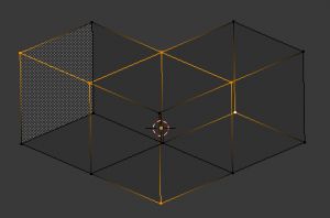
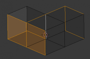
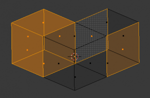
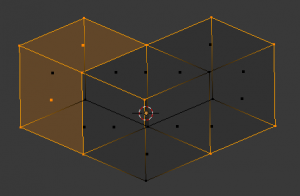
See (Vertices mode example), (Edges mode example), (Faces mode example) and (Mixed mode example) for examples of the different modes.


