「Doc:2.6/Manual/3D interaction/Navigating/3D View」の版間の差分
(→Quad View) |
細 (1版 をインポートしました) |
(相違点なし)
| |
2018年6月29日 (金) 04:44時点における最新版
Introduction
To be able to work in the three dimensional space that Blender uses, you must be able to change your viewpoint as well as the viewing direction of the scene. While we will describe the 3D View window, most of the other windows have similar functions. For example, it is possible to translate and zoom a Buttons window and its panels.
| Mouse Buttons and Numpad | |
| If you have a mouse with less than three buttons or a keyboard without numpad, please refer to the Keyboard and Mouse page of the manual to learn how to use them with Blender. |
Perspective and Orthographic Views
Mode: All modes
Hotkey: 5 NumPad
Menu: View » Perspective / View » Orthographic
Description
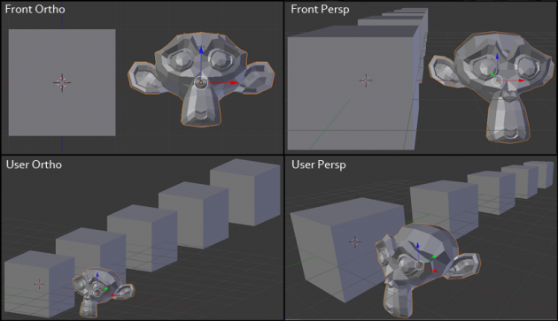
Each 3D viewport supports two different types of projection. These are demonstrated in the Orthographic (left) and perspective (right) projections image below.
Our eye is used to perspective viewing because distant objects appear smaller. Orthographic projection often seems a bit odd at first, because objects stay the same size regardless of their distance. It is like viewing the scene from an infinitely distant point. Nevertheless, orthographic viewing is very useful (it is the default in Blender and most other 3D applications), because it provides a more “technical” insight into the scene, making it easier to draw and judge proportions.
Options
To change the projection for a 3D view, choose the View » Orthographic or the View » Perspective menu entry. The 5 NumPad shortcut toggles between the two modes. Changing the projection for a 3D view does not affect the way the scene will be rendered. Rendering is in perspective by default. If you need to create an orthographic rendering, select the camera, go to the Object Data context and press the Orthographic button in the Lens panel.
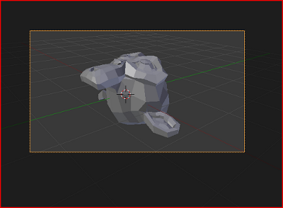
The View » Camera menu entry sets the 3D view to camera mode (0 NumPad). The scene is then displayed as it will be rendered later (see Demonstration of camera view). The rendered image will contain everything within the orange dotted line. Zooming in and out is possible in this view, but to change the viewpoint, you have to move or rotate the camera.
If you have a large scene, viewing it through Camera View may not display all of the Objects in the scene. One possibility may be that the clipping distance of the camera is too low. The camera will only show objects that fall within the clipping range.
Read more about Render perspectives »
Read more about Camera View »
Read more about Camera clipping »
Technical Details
Perspective definition
A perspective view is geometrically constructed by taking a scene in 3D and placing an observer at point O. The 2D perspective scene is built by placing a plane (e.g. a sheet of paper) where the 2D scene is to be drawn in front of point O, perpendicular to the viewing direction. For each point P in the 3D scene a PO line is drawn, passing by O and P. The intersection point S between this PO line and the plane is the perspective projection of that point. By projecting all points P of the scene you get a perspective view.
Orthographic definition
In an orthographic projection, you have a viewing direction but not a viewing point O. The line is then drawn through point P so that it is parallel to the viewing direction. The intersection S between the line and the plane is the orthographic projection of the point P. By projecting all points P of the scene you get the orthographic view.
Rotating the View
Mode: All modes
Hotkey: MMB ![]() / 2 NumPad / 4 NumPad / 6 NumPad / 8 NumPad / CtrlAltWheel
/ 2 NumPad / 4 NumPad / 6 NumPad / 8 NumPad / CtrlAltWheel ![]()
Menu: View » Navigation
Description
Blender provides four default viewing directions: Side, Front, Top and Camera view. Blender uses a right-angled “Cartesian” coordinate system with the Z axis pointing upwards. “Side” corresponds to looking along the X axis, in the negative direction, “Front” along the Y axis, and “top” along the Z axis. The Camera view shows the current scene as seen from the camera view point.
Options
You can select the viewing direction for a 3D viewport with the View menu entries, or by pressing the hotkeys 3 NumPad for “side”, 1 NumPad for “front”, 7 NumPad for “top”. You can select the opposite directions if you hold Ctrl while using the same numpad shortcuts. Finally 0 NumPad gives access to the “camera” viewpoint.
Apart from these four default directions, the view can be rotated to any angle you wish. Click and drag MMB ![]() on the viewport’s area. If you start in the middle of the window and move up and down or left and right, the view is rotated around the middle of the window. Alternatively, if the Emulate 3 button mouse option is select in the User Preferences you can press and hold Alt while dragging LMB
on the viewport’s area. If you start in the middle of the window and move up and down or left and right, the view is rotated around the middle of the window. Alternatively, if the Emulate 3 button mouse option is select in the User Preferences you can press and hold Alt while dragging LMB ![]() in the viewport’s area.
in the viewport’s area.
To change the viewing angle in discrete steps, use 8 NumPad and 2 NumPad (which correspond to vertical MMB ![]() dragging, from any viewpoint), or use 4 NumPad and 6 NumPad (or CtrlAltWheel
dragging, from any viewpoint), or use 4 NumPad and 6 NumPad (or CtrlAltWheel ![]() ) to rotate the scene around the Z global axis from your current point of view.
) to rotate the scene around the Z global axis from your current point of view.
Hotkeys
Remember that most hotkeys affect the active window (the one that has focus), so check that the mouse cursor is in the area you want to work in before your use the hotkeys.
|
TrackBall/Turntable
By default, when you rotate the view as described above, you are using the turntable method. For some users this is intuitive and for others it is not. If you feel you are having difficulties with this style of 3D window rotation you can switch to the “trackball” style. With the trackball style you are rotating the scene as though you are rolling your hand across a “trackball”
The Turntable style is fashioned more like a record player where you have two axes of rotation available, and the world seems to have a better definition of what is “Up” and “Down” in it. The downside to using the Turntable style is that you lose some flexibility when working with your objects. However, you gain the sense of “Up” and “Down” which can help if you are feeling disoriented. Of course you can always switch between the styles depending on what you are working on.
To change the rotation “style”, use the User Preferences window. Click on the Input button and you will see an option for choosing the Orbit style. There are two additional checkboxes for controlling the display in the 3D window in the Interface tab in the User Preferences. Auto Perspective will automatically switch to perspective whenever the view is rotated using MMB ![]() . Rotate Around Selection will rotate the view around the center of the current selection. If there is no selection at that moment (e.g. if you used A to deselect everything), the last selection will be used anyway.
. Rotate Around Selection will rotate the view around the center of the current selection. If there is no selection at that moment (e.g. if you used A to deselect everything), the last selection will be used anyway.
Panning the View
Mode: All modes
Hotkey: ⇧ ShiftMMB ![]() / Ctrl2 NumPad / Ctrl4 NumPad / Ctrl6 NumPad / Ctrl8 NumPad / ⇧ ShiftAltLMB
/ Ctrl2 NumPad / Ctrl4 NumPad / Ctrl6 NumPad / Ctrl8 NumPad / ⇧ ShiftAltLMB ![]()
Menu: View → Navigation
Description
To pan the view, hold down ⇧ Shift and drag MMB ![]() in the 3D Viewport. For discrete steps, use the hotkeys Ctrl8 NumPad, Ctrl2 NumPad, Ctrl4 NumPad and Ctrl6 NumPad as with rotating (note: you can replace Ctrl by ⇧ Shift). For those without a middle mouse button, you can hold ⇧ Shift Alt while dragging with LMB
in the 3D Viewport. For discrete steps, use the hotkeys Ctrl8 NumPad, Ctrl2 NumPad, Ctrl4 NumPad and Ctrl6 NumPad as with rotating (note: you can replace Ctrl by ⇧ Shift). For those without a middle mouse button, you can hold ⇧ Shift Alt while dragging with LMB ![]() .
.
Zooming the View
Description
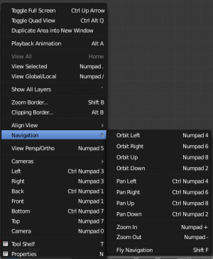
You can zoom in and out by holding down Ctrl and dragging MMB ![]() . The hotkeys are + NumPad and - NumPad. The View » Navigation sub-menu holds these functions too as well. Refer to the 3D viewport’s View menu image above for more information.
. The hotkeys are + NumPad and - NumPad. The View » Navigation sub-menu holds these functions too as well. Refer to the 3D viewport’s View menu image above for more information.
If you have a wheel mouse, you can perform all of the actions in the 3D viewport that you would do with + NumPad and - NumPad by rotating the Wheel ![]() . To zoom a Buttons window, hold CtrlMMB
. To zoom a Buttons window, hold CtrlMMB ![]() and move your mouse up and down.
and move your mouse up and down.
If You Get Lost…
If you get lost in 3D space, which is not uncommon, two hotkeys will help you: ↖ Home changes the view so that you can see all objects (View » View All menu entry), while . NumPad zooms the view to the currently selected objects when in perspective mode (View » View Selected menu entry).
|
Zoom Border
The Zoom Border tool allows you to specify a rectangular region and zoom in so that the region fills the 3d view.
You can access this through the View menu, or the shortcut ⇧ ShiftB then click and drag rectangle to zoom in.
Dolly the View
Description
In most cases its sufficient to zoom the view to get a closer look at something, however you may notice that at a certain point you cannot zoom any closer.
This is because Blender stores a view-point thats used for orbiting and zooming, This works well in many cases but sometimes you want to move the view-point to a different place - This is what Dolly supports, allowing you to transport the view from one place to another.
You can dolly back and fourth by holding down Ctrl⇧ Shift and dragging MMB ![]() .
.
Aligning the View
Align View
These options allow you to align and orient the view in different ways. They are found in the View Menu
- Align View to Selected menu
- These options align your view with specified local axes of the selected object or, in Edit mode, with the normal of the selected face.
- Top ⇧ Shift7 NumPad
- Bottom ⇧ ShiftCtrl7 NumPad
- Front ⇧ Shift1 NumPad
- Back ⇧ ShiftCtrl1 NumPad
- Right ⇧ Shift3 NumPad
- Left ⇧ ShiftCtrl3 NumPad
- Center Cursor and View All (⇧ ShiftC)
- moves the cursor back to the origin and zooms in/out so that you can see everything in your scene.
- Align Active Camera to View, CtrlAlt0 NumPad
- Gives your active camera the current viewpoint
- View selected, . NumPad
- Focuses view on currently selected object/s by centering them in the viewport, and zooming in until they fill the screen.
- Center view to cursor, Alt↖ Home
- Centers view to 3D-cursor
View Selected
- See above
View All ↖ Home
- Frames all the objects in the scene, so they are visible in the viewport.
Local and Global View
You can toggle between Local and Global view by selecting the option from the View Menu or using the shortcut / NumPad. Local view isolates the selected object or objects, so that they are the only ones visible in the viewport. This is useful for working on objects that are obscured by other ones, or have heavy geometry. Press / NumPad to return to Global View.
Quad View
Mode: All modes
Hotkey: CtrlAltQ
Menu: View » Toggle Quad View
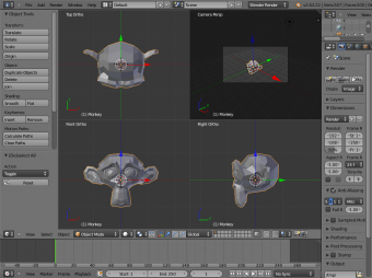
Toggling Quad View will split the 3D window into 4 views: Top Ortho, Front Ortho, Right Ortho and Camera / User View. This view will allow you to instantly see your model from a number of view points. In this arrangement, you can zoom and pan each view independently but you cannot rotate the view. Note that this is different from splitting the windows and aligning the view manually. In Quad View, the four views are still part of a single 3D window. If you want to be able to rotate each view, you will need to split the 3D window into separate windows.
Read more about splitting windows »
View Clipping Border
Mode: All modes
Hotkey: AltB
Menu: View » Set Clipping Border
Description
To assist in the process of working with complex models and scenes, you can set the view clipping to visually isolate what you’re working on.
Once clipping is used, you will only see whats inside a volume you've defined. Tools such as paint, sculpt, selection, transform-snapping etc. will also ignore geometry outside the clipping bounds.
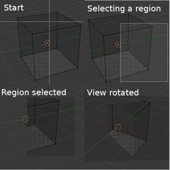
Once activated with AltB, you have to draw a rectangle with the mouse, in the wanted 3D view. The created clipping volume will then be:
- A right-angled parallelepiped (of infinite length) if your view is orthographic.
- A rectangular-based pyramid (of infinite height) if your view is in perspective.
To delete this clipping, press AltB again.
Example
The Region/Volume clipping image shows an example of using the clipping tool with a cube. Start by activating the tool with AltB (upper left of the image). This will generate a dashed cross-hair cursor. Click with the LMB ![]() and drag out a rectangular region shown in the upper right. Now a region is defined and clipping is applied against that region in 3D space. Notice that part of the cube is now invisible or clipped. Use the MMB
and drag out a rectangular region shown in the upper right. Now a region is defined and clipping is applied against that region in 3D space. Notice that part of the cube is now invisible or clipped. Use the MMB ![]() to rotate the view and you will see that only what is inside the pyramidal volume is visible. All the editing tools still function as normal but only within the pyramidal clipping volume.
to rotate the view and you will see that only what is inside the pyramidal volume is visible. All the editing tools still function as normal but only within the pyramidal clipping volume.
The dark gray area is the clipping volume itself. Once clipping is deactivated with another AltB, all of 3D space will become visible again.
Mode: All modes
Hotkey: ⇧ ShiftF
Description
When you have to place the view, normally you do as described above.
However, there are cases in which you really prefer to just navigate your model, especially if it’s very large, like environments or some architectural model. In these cases viewing the model in perspective mode has limitations, for example after zooming a lot of panning is extremely uncomfortable and difficult, or you apparently cannot move the camera any nearer. As an example, try to navigate to a very distant object in the view with traditional methods (explained above) and see what you can get.
With Walk mode and Fly mode you move, pan and tilt, and dolly the camera around without any of those limitations.
In the User Preferences window select the navigation mode you want to use as default when invoking the View Navigation operator. Alternatively you can call the individual modes from the View Navigation menu.
