「利用者:Fade/Doc:2.6/Manual/Modeling/Curves/Editing/Advanced」の版間の差分
細 (1版 をインポートしました) |
|
(相違点なし)
| |
2018年6月29日 (金) 06:06時点における最新版
Curve Deform
Curve Deform allows you to control mesh deformation using a curve. By parenting a mesh object to a curve, you can deform the mesh along the curve by moving the mesh along, or perpendicular to, the dominant axis. This is useful to make an object follow a complex path, e.g. a sheet of paper inside a printer or the a film inside an old camera.
Curve Deform operates via the Global Tranformation Orientation axes (X, Y, or Z). The Deformation axis (dominant axis) can be set and moving the Object along this axis will cause the Object to move along the curve and deform according to the shape of the curve.
Moving the object perpendicular to the deformation axis will cause it to move away from or closer to the curve. When you move the object beyond the curve endings the object will continue to deform based on the direction vector of the curve endings. If the “curve path” is 3D, the Tilt value of its control points will be used (see the Extrusion section below) to twist the “curved” object around it.
Use modifiers!
The Curve Deform relationship is now also a modifier, called Curve. The Curve modifier function acts the same as its counterpart, except that when the modifier is used, the “dominant axis” is set inside its properties – and the Track X/Y/Z buttons no longer have an effect on it. Plus you have some additional options, like the possibility of only curving one of the vertex groups of a mesh. For more information, see the Curve Modifier page.
|
Interface
| Curve Positioning Tip | |
| Try to position your Object over the curve before adding the Curve Deform. This gives the best control over how the deformation works. |
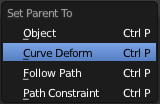
When parenting an object (mesh, curve, meta, …) to a curve (CtrlP), you will be presented with a menu (Make Parent menu).
By selecting Curve Deform, you enable the curve deform function on the mesh object.
The dominant axis setting is set on the mesh object. By default the dominant axis in Blender is Y. This can be changed by selecting one of the Track X, Y or Z buttons in the Anim Panel, (Anim settings panel), in Object context (F7).
Cyclic (or closed) curves work as expected where the object deformations traverse along the path in cycles. Note however that when you have more than one curve in the “parent” object, its “children” will only follow the first one.
The Stretch curve option allows you to let the mesh object stretch, or squeeze, over the entire curve. This option is in Editing Context (F9), for the “parent” curve. See Curve and Surface panel.
Curve editing
For a review of the basic properties that can be edited please consult the geometry section of the Curves page
Read more about Curves - Geometry ».
Extrusion
Mode: Object or Edit mode
Panel: Curve and Surface (Editing context, F9)
Advanced Extrusion
These extrusions use one or two additional curve objects, to create very complex organic shapes.
To enable this type of extrusion, you have to type a valid curve object name in the BevOb field of the curve you are going to use as the “spinal column” of your extrusion. The “bevel” curve will control the cross section of the extruded object. Whether the BevOb curve is 2D or 3D has no importance, but if it is closed, it will create a “tube-like” extrusion; otherwise you will get a sort of gutter or slide object…
The object is extruded along the whole length of all internal curves. By default, the width of the extrusion is constant, but you have two ways to control it, the Radius property of control points, and the “taper” object.
The Radius of the points is set using the Shrink/Fatten Radius transform tool (AltS, or Curve » Transform » Shrink/Fatten Radius), or with the Set Radius entry in the Specials menu (W). Here again, you unfortunately cannot visualize anywhere the Radius of a given control point…
The Radius allows you to directly control the width of the extrusion along the “spinal” curve. As for Tilt (see above), you can choose the interpolation algorithm used for Bézier curves, in the Radius Interpolation drop-down list of the Curve Tools panel.
But you have another, more precise option: the “taper” object. As for the “bevel” one, you set its name in the TaperOb field of the main curve – it must be an open curve. The taper curve is evaluated along the local X axis, using the local Y axis for width control. Note also that:
- The taper is applied independently to all curves of the extruded object.
- Only the first curve in a TaperOb is evaluated, even if you have several separated segments.
- The scaling starts at the first control-point on the left and moves along the curve to the last control-point on the right.
- Negative scaling, (negative local Y on the taper curve) is possible as well. However, rendering artifacts may appear.
- It scales the width of normal extrusions based on evaluating the taper curve, which means sharp corners on the taper curve will not be easily visible. You’ll have to heavily level up the resolution (DefResolU) of the base curve.
- With closed curves, the taper curve in TaperOb acts along the whole curve (perimeter of the object), not just the length of the object, and varies the extrusion depth. In these cases, you want the relative height of the TaperOb Taper curve at both ends to be the same, so that the cyclic point (the place where the endpoint of the curve connects to the beginning) is a smooth transition.
Last but not least, with 3D “spinal” curves, the Tilt of the control points can control the twisting of the extruded “bevel” along the curve!
Examples
TODO: add some “simple” extrusion examples.
TODO: add some “bevel” extrusion with Radius examples.
Let’s taper a simple curve circle extruded object using a taper curve. Add a curve, then exit Edit
mode. Add another one (a closed one, like a circle); call it “BevelCurve”, and enter its name in the BevOb field of the first curve (Editing context F9, Curve and Surface panel). We now have a pipe. Add a third curve while in Object mode and call it “TaperCurve”. Adjust the left control-point by raising it up about 5 units.
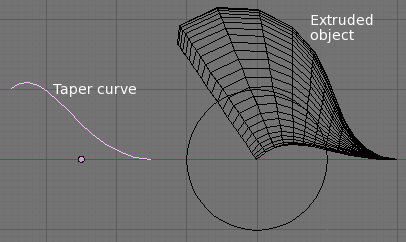
Now return to the Editing context, and edit the first curve’s TaperOb field in Curve and Surface panel to reference the new taper curve which we called “TaperCurve”. When you hit enter the taper curve is applied immediately, with the results shown in (Taper extruded curve).
You can see the taper curve being applied to the extruded object. Notice how the pipe’s volume shrinks to nothing as the taper curve goes from left to right. If the taper curve went below the local Y axis the pipe’s inside would become the outside, which would lead to rendering artifacts. Of course as an artist that may be what you are looking for!
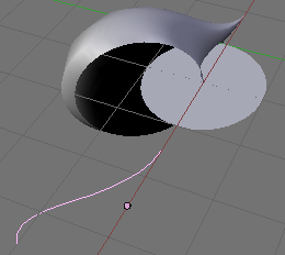
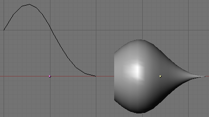
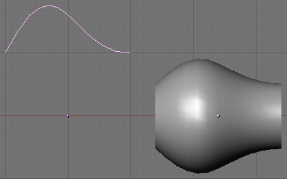
In (Taper example 1) you can clearly see the effect the left taper curve has on the right curve object. Here the left taper curve is closer to the object center and that results in a smaller curve object to the right.
In (Taper example 2) a control point in the taper curve to the left is moved away from the center and that gives a wider result to the curve object on the right.
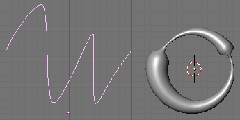
In (Taper example 3), we see the use of a more irregular taper curve applied to a curve circle.
TODO: add some “bevel” extrusion with Tilt examples.
