「Doc:2.6/Manual/Textures/Mapping/UV/Unwrapping」の版間の差分
(→Getting Started) |
(相違点なし)
|
2014年7月13日 (日) 08:07時点における版
Page status (reviewing guidelines)
Proposed split
Images
additional examples
|
UV Mapping a Mesh
The first step is to unwrap your mesh. You want to unwrap when you feel your mesh is complete with respect to the number of faces it needs to have. If you do add faces or subdivide existing faces when a model is already unwrapped, Blender will add those new faces for you, but you may need to do additional mapping or editing. In this fashion, you can use the UV Texture image to guide additional geometry changes.
This section covers techniques for Mapping Uvs. The next sections cover Editing UVs, followed by methods of Managing UV Layouts, and Applying Images to UVs.
About UVs
Every point in the UV map corresponds to a vertex in the mesh. The lines joining the UVs correspond to edges in the mesh. Each face in the UV map corresponds to a mesh face.
Each face of a mesh can have many UV Textures. Each UV Texture can have an individual image assigned to it. When you unwrap a face to a UV Texture in the UV/Image Editor, each face of the mesh is automatically assigned four UV coordinates: These coordinates define the way an image or a texture is mapped onto the face. These are 2D coordinates, which is why they're called UV, to distinguish them from XYZ coordinates. These coordinates can be used for rendering or for real-time OpenGL display as well.
Every face in Blender can have a link to a different image. The UV coordinates define how this image is mapped onto the face. This image then can be rendered or displayed in real time. A 3D window has to be in "Face Select" mode to be able to assign Images or change UV coordinates of the active Mesh Object. This allows a face to participate in many UV Textures. A face at the hairline of a character might participate in the facial UV Texture, and in the scalp/hair UV Texture.
These are described more fully in the next sections.
Getting Started
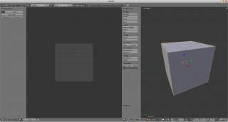
By default, meshes are not created with UVs. First you must map the faces, then you can edit them. The process of unwrapping your model is done within Edit Mode in the 3D View window. This process creates one or more UV Islands in the UV/Image Editor window.
To begin, choose the UV Editing screen layout from the selection list at the top of your screen in the User Preferences window header. This sets one of the panes to show you the UV/Image Editor window (⇧ ShiftF10), and the other pane to the 3D window (⇧ ShiftF5).
Enter edit mode, as all unwrapping is done in Edit mode. You can be in vertex, face, or edge selection mode.
Workflow
The process for unwrapping is straightforward, but there are tons of options available, each of which dramatically affect the outcome of the unwrap. By understanding the meaning behind the options, you will become more efficient at unwrapping. The process is:
- Mark Seams if necessary
- Select all of the mesh components
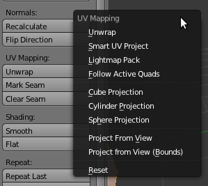
- Select a UV mapping method from the UV Unwrap menu
- Adjust the unwrap settings
- Add a test image to see if there will be any distortion. See Applying Images to UVs
- Adjust UVs in the UV editor. See Editing UVs
Mapping Types
Blender offers several ways of mapping UVs. The simpler projection methods use formulas that map 3d space onto 2d space, by interpolating the position of points toward a point/axis/plane through a surface. The more advanced methods can be used with more complex models, and have more specific uses.
Basic:
- Cube
- Maps the mesh onto the faces of a cube, which is then unfolded.
- Sphere
- Projects the UVs onto a spherical shape. Useful only for spheres or spherical shapes, like eyes, planets, etc.
- Cylinder
- Projects UVs onto a cylindrical surface.
- Project from View
- Takes the current view in the 3D viewport and flattens it as it appears.
Advanced:
- Unwrap
- Useful for organic shapes. Smooths the mesh into a flat surface by cutting along seams.
- Smart UV Project
- Breaks the mesh into islands based on an angle threshold.
- Lightmap Pack
- Separates each face and packs them onto the UV grid.
- Follow Active Quads
- Follow UV from active quads along continuous face loops.
You can also reset UVs, which maps each face to fill the UV grid, giving each face the same mapping.
If we were to use an image that was tileable, the surface would be covered in a smooth repetition of that image, with the image skewed to fit the shape of each individual face. Use this unwrapping option to reset the map and undo any unwrapping (go back to the start).
Basic Mapping
Based on the fundamental geometry of the object, and how it is being viewed, the Mesh->UV Unwrap->Cube, Cylinder, and Sphere UV Calculations attempt to unfold the faces for you as an initial best fit. Here, the view from the 3D window is especially important. Also, the settings for cube size or cylinder radius (Editing buttons, UV Calculation panel) should be set (in Blender units) to encompass the object.
The following settings are common for the Cube, Cylinder, and Sphere mappings:
- Correct Aspect
- Map UVs taking image aspect ratios into consideration. If an image has already been mapped to the texture space that is non-square, the projection will take this into account and distort the mapping to appear correct.
- Clip to Bounds
- Any UVs that lie outside the 0 to 1 range will be clipped to that range by being moved to the UV space border it is closest to.
- Scale to Bounds
- If the UV map is larger than the 0 to 1 range, the entire map will be scaled to fit inside.
Cube
Cube mapping projects s mesh onto six separate planes, creating 6 UV islands. In the UV editor, these will appear overlapped, but can be moved. See Editing UVs.
Cube Size
- Set the size of the cube to be projected onto.
Cylinder and Sphere
Cylindrical and Spherical mappings have the same settings. The difference is that a cylindrical mapping projects the UVs on a plan toward the cylinder shape, while a spherical map takes into account the sphere’s curvature, and each latitude line becomes evenly spaced.
Normally, to unwrap a cylinder (tube) as if you slit it lengthwise and folded it flat, Blender wants the view to be vertical, with the tube standing 'up'. Different views will project the tube onto the UV map differently, skewing the image if used. However you can set the axis on which the calculation is done manually. This same idea works for the sphere mapping:
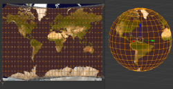
Recall the opening cartographer's approaching to mapping the world? Well, you can achieve the same here when unwrapping a sphere from different perspectives. Normally, to unwrap a sphere, view the sphere with the poles at the top and bottom. After unwrapping, Blender will give you a Mercator projection; the point at the equator facing you will be in the middle of the image. A polar view will give a very different but common projection map. Using a Mercator projection map of the earth as the UV image will give a very nice planet mapping onto the sphere.
- Direction
- View on Poles
- Use when viewing from the top (at a pole) by using an axis that is straight down from the view
- View on Equator
- Use if view is looking at the equator, by using a vertical axis
- Align to Object
- Uses the object's transform to calculate the axis
- Align
- Select which axis is up
- Polar ZX
- Polar 0 is on the x axis
- Polar ZY
- Polar 0 is on the y axis
- Radius
- The radius of the cylinder to use
Project From View
In the 3D window, the Face->Unwrap UVs->Project from View option maps the face as seen through the view of the 3D window it was selected from. It is almost like you had x-ray vision or squashed the mesh flat as a pancake onto the UV map. Use this option if you are using a picture of a real object as a UV Texture for an object that you have modeled. You will get some stretching in areas where the model recedes away from you.
Using Project from View (Bounds) will do the same as above, but scales the UVs to the bounds of the UV space.
Resetting UVs
In the 3D window, Face->Unwrap->Reset maps each selected face to the same area of the image, as previously discussed. To map all the faces of an object (a cube, for example) to the same image, select all the faces of the cube, and unwrap them using the Reset menu option.
Advanced Mapping
Unwrapping Using Seams
For many cases, using the Unwrap calculations of Cube, Cylinder, Sphere, or best fit will produce a good UV layout. However, for more complex meshes, especially those with lots of indentations, you may want to define a seam to limit and guide any of the unwrapping processes discussed above.
Just like in sewing, a seam is where the ends of the image/cloth are sewn together. In unwrapping, the mesh is unwrapped at the seams. Think of this method as peeling an orange or skinning an animal. You make a series of cuts in the skin, then peel it off. You could then flatten it out, applying some amount of stretching. These cuts are the same as seams.
When using this method, you need to be aware of how much stretching there is. The more seams there are, the less stretching there is, but this is often an issue for the texturing process. It’s a good idea to have as few seams as possible while having the least amount of stretching. Try to hide seams where they will not be seen. In productions where 3d Paint is used, this becomes less of an issue, as projection painting can easily deal with seams, as opposed to 2d texturing, where it is difficult to match the edges of different UV islands.
The workflow is the following:
- Create seams. A seam is marked in Edit mode by selecting edges to make the seam and then issuing the command to Mark Seam.
- Unwrap
- Adjust seams and repeat
- Manually adjust UVs. See the next section on Editing UVs.
Marking Seams
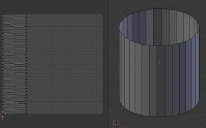
To add an edge to a seam, simply select the edge and CtrlE Mark Seam. To take an edge out of a seam, select it, CtrlE and Clear Seam.
In the example to the right, the back-most edge of the cylinder was selected as the seam (to hide the seam), and the default unwrap calculation was used. In the UV/Image Editor window, you can see that all the faces are nicely unwrapped, just as if you cut the seam with a scissors and spread out the fabric.
When marking seams, you can use the Select->Linked Faces or CtrlL in Face Select Mode to check your work. This menu option selects all faces connected to the selected one, up to a seam. If faces outside your intended seam are selected, you know that your seam is not continuous. You do not need continuous seams, however, as long as they resolve regions that may stretch.
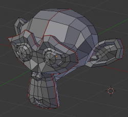
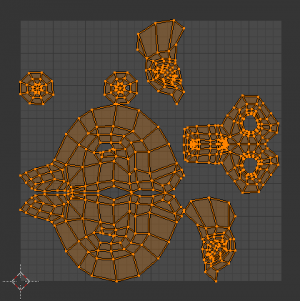
Just as there are many ways to skin a cat, there are many ways to go about deciding where seams should go. In general though, you should think as if you were holding the object in one hand, and a pair of sharp scissors in the other, and you want to cut it apart and spread it on the table with as little tearing as possible. Note that we seamed the outside edges of her ears, to separate the front from the back. Her eyes are disconnected sub-meshes, so they are automatically unwrapped by themselves. A seam runs along the back of her head vertically, so that each side of her head is flattened out.
Another use for seams is to limit the faces unwrapped. For example, when texturing a head, you don't really need to texture the scalp on the top and back of the head since it will be covered in hair. So define a seam at the hairline. Then, when you select a frontal face, and then select linked faces before unwrapping, the select will only go up to the hairline seam, and the scalp will not be unwrapped.
When unwrapping anything that is bilateral, like a head or a body, seam it along the mirror axis. For example, cleave a head or a whole body right down the middle in front view. When you unwrap, you will be able to overlay both halves onto the same texture space, so that the image pixels for the right hand will be shared with the left; the right side of the face will match the left, etc.
Finally, remember that you don't have to come up with "one unwrapping that works perfectly for everything everywhere." As we'll discuss later, you can easily have multiple UV unwrappings, using different approaches in different areas of your mesh.
Unwrap
Begin by selecting all faces to be unwrapped in the 3D View. With our faces selected, it is now time to unwrap them. In the 3D View, select Mesh->UV Unwrap or U and select Unwrap.
You can also do this from the UV/Image Editor window with command UVs->Unwrap or command E. This method will unwrap all of the faces and reset previous work. The UVs menu will appear in the UV/Image Editor window after unwrapping has been performed once.
The Face->Unwrap->Unwrap option unwraps the faces of the object to provide the 'best fit' scenario based on how the faces are connected and will fit within the image, and takes into account any seams within the selected faces. If possible, each selected face gets its own different area of the image and is not tucked under any other faces. If all faces of an object are selected, then each face is mapped to some portion of the image.
Blender has two ways of calculating the unwrapping. They can be selected in the tool setting in the tool panel in the 3D View.
- Angle Based
- This method gives a good 2d representation of a mesh.
- Conformal
- Uses LSCM (Least Squared Conformal Mapping). This usually gives a less accurate UV mapping than Angle Based, but works better for simpler objects.
- Fill Holes
- Activating Fill Holes will prevent overlapping from occurring and better represent any holes in the UV regions.
- Correct Aspect
- Map UVs taking image aspect into account
- Use Subsurf Modifier
- Map UVs taking vertex position after subsurf modifier into account
- Margin
- Space between UV islands
This point is crucial to understanding mapping later on: a face's UV image texture only has to use part of the image, not the whole image. Also, portions of the same image can be shared by multiple faces. A face can be mapped to less and less of the total image.
Smart UV Project
Smart UV Project, (previously called the Archimapper) gives you fine control over how automatic seams should be created, based on angular changes in your mesh. This method is good for simple and complex geometric forms, such as mechanical objects or architecture.
This function examines the shape of your object, the faces selected and their relation to one another, and creates a UV map based on this information and settings that you supply.
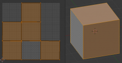
In the example to the right, the Smart Mapper mapped all of the faces of a cube to a neat arrangement of 3 sides on top, 3 sides on the bottom, for all six sides of the cube to fit squarely, just like the faces of the cube.
For more complex mechanical objects, this tool can very quickly and easily create a very logical and straightforward UV layout for you.
The Tool Settings panel in the Tool Shelf allows the fine control over how the mesh is unwrapped:
- Angle Limit
- This controls how faces are grouped: a higher limit will lead to many small groups but less distortion, while a lower limit will create fewer groups at the expense of more distortion.
- Island Margin
- This controls how closely the UV islands are packed together. A higher number will add more space in between islands.
- Area Weight
- Weight projection's vector by faces with larger areas
Lightmap
Lightmap Pack takes each of a mesh's faces, or selected faces, and packs them into the UV bounds. Lightmaps are used primarily in gaming contexts, where lighting information is baked onto texture maps, when it is essential to utilize as much UV space as possible. It can also work on several meshes at once. It has several options that appear in the Tool Shelf:
You can set the tool to map just Selected Faces or All Faces if working with a single mesh.
The Selected Mesh Object option works on multiple meshes. To use this, in Object Mode select several mesh objects, then go into Edit Mode and activate the tool.
- Share Tex Space
- This is useful if mapping more than one mesh. It attempts to fit all of the objects' faces in the UV bounds without overlapping.
- New UV Layer
- If mapping multiple meshes, this option creates a new UV layer for each mesh. See Managing the Layout.
- New Image
- Assigns new images for every mesh, but only one if Shared Tex Space is enabled.
- Image Size
- Set the size of the new image.
- Pack Quality
- Pre-packing before the more complex Box packing.
- Margin
- This controls how closely the UV islands are packed together. A higher number will add more space in between islands.
Follow Active Quads
The Face->Unwrap->Follow Active Quads takes the selected faces and lays them out by following continuous face loops, even if the mesh face is irregularly shaped. Note that it does not respect the image size, so you may have to scale them all down a bit to fit the image area.
Edge Length Mode:
- Even
- Space all UVs evenly.
- Length
- Average space UV's edge length of each loop.
Please note that it is the shape of the active quad in UV space that is being followed, not its shape in 3d space. To get a clean 90-degree unwrap make sure the active quad is a rectangle in UV space before using "Follow active quad".
