Dev:Ref/Requests/Editing
目次
- 1 Edge and Angle Numeric Allocator
- 2 Pen Vertex Organizer
- 3 Limit numerics to visible
- 4 Transform slightly more parametric
- 5 Cage Retopo and other Retopo Improvements
- 6 modeling tool based on armature
- 7 Editing Lattices For Characters
- 8 Features for technical design
- 9 3D Manga
- 10 Selection requests
- 11 Component Deleting
- 12 Integrate Widget editing and old-school mesh editing
- 13 Linear Combination for Joining Faces/Adding Vertices
- 14 Polygonal Surface Simplification
- 15 Fgons v.s. Ngons
- 16 Colored Wireframes
- 17 SubDivImprovements
- 18 PET constrained in X, Y, or Z axis
- 19 Scaling, Rotating, Grabbing vertices constrained to View coordinates
- 20 Aligning of a vertex(es) to 3D Cursor
- 21 Absolut values in "Transformation Properties" window
- 22 Blender Keymap
- 23 Wanted features from Wings3D
- 24 duplicating an object when moving with the grab function by keeping shift pressed.
- 25 Pinning vertices in edit mode.
- 26 Arbitrary Rotation Axis
- 27 Clipping volumes
- 28 Visible edges in object mode
- 29 DoubleClick to put a vertex on a line & more:
- 30 Mesh & Object Modifier
- 31 Define Shear axis
- 32 Better bevelObject
- 33 Nurbs- and -Surface-Curve Conversion
- 34 Proportional edit type: Follow
- 35 Spline Tools Integration In UV/Image Editor For Masking
- 36 DupliVerts as a Modifier
- 37 Text Editor
- 38 View Frustum Culling Modifier
- 39 Summit sides bribes
- 40 Precision instrument
- 41 2D Image Conversion To 3D
- 42 3D Charts and Graphs with Animation
- 43 poly spline type mesh interpolating option
Edge and Angle Numeric Allocator
There needs to be a completed, debugged maximum decimal place accuracy numeric tool to edit edit mode selected edges by means of in-place length. Two selected, vertex touching edges could also be selected and adjusted by their between angle. The tool also should read angles already in place via appropriate selecting in edit mode.
Pen Vertex Organizer
I don't know if this is the place to talk about this... My english is very poor.
I have an idea for one editing tool.
Call Pen Vertex Organizer.
You can see how it work in this image:
http://www.overmaquetes.com.br/PEN_ORGANIZER.jpg
I think this one can help so much in our work.
Hugs! Renato Meneses = renatoMM user --User:RenatoMM 26 Marc 2013
Limit numerics to visible
Today I have noticed, that if the numerics (any of them) are turned on, the numbers are visible, even the face/edge/angle is unseen (limit selection to visible is turned on). Personally I don't need this feature toggleable, it's on who codes this. --User:HadaHector 19 Marc 2013
Transform slightly more parametric
When you transform a n objects position via the transform box (n) it would be nice that if you entered an equation, such as x + y/2 (where x and y are numbers) that when you went back to editing the position via the transform box it remembered the equation. When you moved it using G it could just go back to a position. Fake/Jak_o_Shadows
Cage Retopo and other Retopo Improvements
Currently, the retopo-function is very useful, and allows a given user to define exactly what they want, rather than using the default conversion-methods, which, although useful, can result in inconvenient poly-counts and other workability-problems. With the current Blender build (2.44), a user has to do four seperate mappings to remap an object. This does give the most control over where verticies are placed, and should stay in the next build, but there also should be a faster way.
Here, the verticies would converge on a single point, centered according to what the median-point/3Dcursor/object-center -setting is assigned to. Probably most of the scripting for it could come from a combination of the current Boolean operations/modifiers and the Retopo -programming. Interface could be as simple as a "cage retopo"-botton next to the normal retopo button-toggle. The tooltip would say something like "use pivot-settings, then select vertecies to collapse."
With this method, if using a highly subdivided UVsphere, say, almost-overlapping vertecies might become a problem. A utility to remap veticies to within a certain edgelength while keeping them on the target to map on.
--CronoCat 2 June 2001 12:52 Mountain
modeling tool based on armature
It would be nice to have the possibility to create mesh based on armature drawing , this would transform the armature system into a nice modeling tool , a bit like Zsphere from Zbrush but with support of vertex groups if possible .
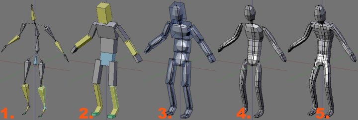
Here's a screen of how i see it :
1. Start by making a simple armature.
2. Change the drawing of the armature into B-bone and change their size with alt+s(we can already do this).
3. Turn on "subsurfaced B-bone" and ...
4. ...go into "B-bone editing mode" , here we will need a tool to easily bridge B-bone like an hotkey for "bridge selected chain of bone".
5. we would be able to edit the bones shape like any other mesh object (extrude ; loopcut ;etc...), this while keeping the vertex groups (based on B-bones).
--kaeru 03:24, 12 January 2007 (CET)
Editing Lattices For Characters
What is greatly needed (for animation purposes) is the ability to edit the base shape of a lattice object. In the following image, you can see how the lattice doesn't really fit around the shape of this character's hip. I'm not going to show it from the side, but you can assume it's an equally bad fit from that angle as well.
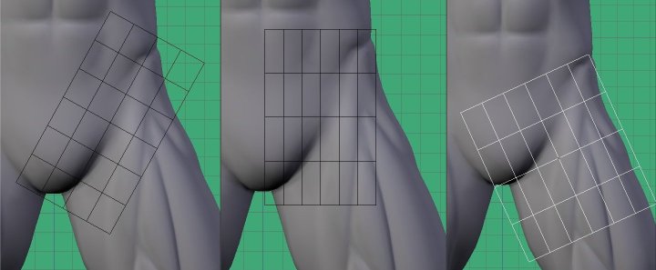
But once it's edited, we could have much greater control.
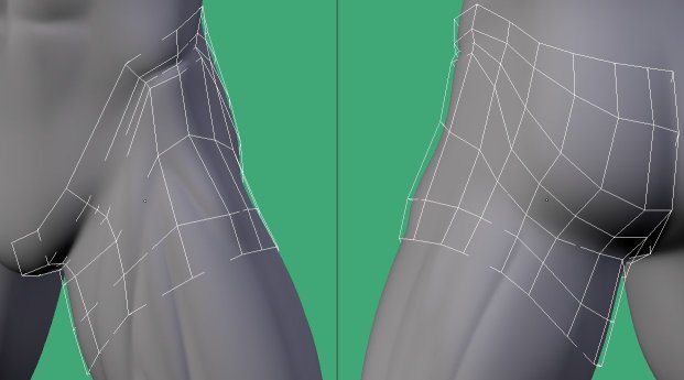
If this shape were the base shape of the lattice--meaning it does not cause any deformation to the mesh--then the user would gain more control for the various deformations.
Using the new shapes UI, it could be made so that shape 1 of a lattice object never causes deformation, no matter how much it is edited. Only in the lattice's other shapes, would deformation result. This way, no new UI buttons need to be added. All shapes would be relative to shape 1.
-- Wavez - 4 May 2006
Features for technical design
Numerical Input for Techdraw
The current Techdraw system is helpful for figuring out whether you have the right geometry, be it edge length, angles, crease location, seamwork, surface area, or what have you. The trouble with it is that if you find out that there s a problem, Techdraw is as of now unhelpful for correcting it, as there are too many numbers in the way when you try to move vertices around. The numbers are also hard to interperet when moving say, a single vertex, much less three or four.
For my examples, I'll be focusing on the angle display.
Here's what I mean when I say that it's hard to see or interperet the numbers: Click Here and Here
Perhaps the system for keyboard/number input would be set up so one vertex could be designated to move, while the rest, although still remaining selected, could stay still. This would save on interperetive programming (the script wouldn't have to figure out which vertex/vertices to move.) This could be done by maybe having a user hold down an unused key to select the vertex he/she wants to move, without deselecting the other vertices and losing the numerical display for the exact angles/edgelengths/etc.
The proposed system will allow users to easily move vertices around and know the angles/edgelength/other Techdraw stuff without having a screen inundated with numbers, and will also have complete control over an exact angle by allowing keyboard input with Techdraw.
The "too many numbers" problem can be approached in two ways, either one will work.
The first method that came to mind was a three-stage selection system, so that certain vertices could be selected to simply constrain data displayed on screen, certain vertices could be selected for translation, rotation, or resizing, and the rest would be unselected and inactive.
Another method might be to have a "always display data for this intersection/edge/corner/face" button. That way, a user could select say, a corner for which he/she wanted data, and then lock it so it would show those data until released. That way, the user could edit any part of the mesh, and the data would still be there no matter what (unless part of the designated structure was deleted, of course.)
Here's what the three-tiered system might look like:
Here's what the lock-in system would look like:
--CronoCat 08:20, 23 November 2005 (CET)
Maybee a script help you to align many vertexes to align one selected vertex.
Please look at http://www.buschhardt.de/pointalign/
It would be great to align or to set values for more than one vertex
-- Test.ThomasBuschhardt#28Aug105 TB
Snap object
In architecture, landscape layout, CAD, etc, it is often necessary to label the distances between the edges/faces of two objects, such as the distance of the outside of a building's wall to the property boundary, or the width and depth of a desktop, or the diagonal dimension of a screen, or the height and width of Mancandy. A Snap object (proposed name) provides (prints, displays) the distance between two (objects, empties, vertices, children, or faces? - not sure which would be easiest to code) within one or two objects in a two- dimensional plane by showing a line connecting orthogonal to the two with the distance in text above or below the line, and the line and text are offset from the connection to be either inside or outside the object or distance. As the (objects/faces/children) move, the distance changes as well as the line stretching. Ideally, the line could have arrowheads on each end. When viewed orthogonally, it looks like a floor blueprint or layout. We could use constraints to track the end of the Snap to an object; but right now the constraint snaps the center of any object, not the endpoints.
Advanced snapping system
proposal for Advanced snapping system
3D Manga
A new tool called *Polyline* that creates individual verticies and the joins them to create a digital manga character with ease. Visit http://www.panebianco3d.com/e_tutorials-japan-3d_p4.htm for where I found the idea. -- BrianClark - 21 Jul 2005
Selection requests
Select Mode
Switching between vertex, edge, and face modes would faster if ctrl+tab worked in the same way that alt+tab works in windows. Press CTRL + tab, tap tab while holding ctrl to switch modes. In this way, one does not need to move the mouse at all to switch between edit modes. -- AndrewGrant - 07 Jul 2005
Don't hose edge selection when switching between Edit mode and Object mode -- AndrewGrant - 11 Jul 2005
I made a patch to allow such cycling. (https://projects.blender.org/tracker/?group_id=9&atid=127&func=detail&aid=4916) It was rejected though because it is not intuitive and there are better alternatives, such as radial menu, available.
--BeBraw 18:40, 5 October 2006 (CEST)
Mouse click and hold for "Box" command.
I would really like to see the bkey "box" command replaced by a simple mouse click and hold. Currently, a mouse click will select and grab a single vertex when I really want to select multiple vertices and not grab them. The gkey is for grabbing and manipulating. The mouse click should act like the bkey not the grab command.
-- power_blend - 02 April 2005
Then you would lose the ability to use gestures to manipulate objects. --i80and 20:54, 6 November 2006 (CET)
Select a named group of objects
Its very useful on a other 3D application called 3dmax to named group of objects for selecting. Grouping can also freeze the objects in the group and draw a cube around all objects.
-- ThomasBuschhardt - 28 Aug 2005
Select "unused" vertexes
Sometimes its nice if I could select all vertexes, these without connection to edge or face.
-- ThomasBuschhardt - 28 Aug 2005
a feature proposal lists and illustrates a few mesh modelling issues, some probably already mentioned here too, http://bellorum.50webs.com/feat_props.html
Component Deleting
A person needs to be able to quickly modify how the surface of a polygonal mesh is constructed in order to maintain a good clean mesh. Edges often need to be deleted, rotated, and created. A user should be able to quickly do all these things. Therefore...
A user should be able to delete an edge without hosing any faces.
Pressing the delete key should delete the component selected, the popup menu is redundant and slows you down. I suppose some users may find the popup menu too usefull to abandon completely, so I would suggest keeping it as CTRL+DELETE. Otherwise Blender is smart enought to figure out what you want to delete base on component selection. -- AndrewGrant - 07 Jul 2005
Integrate Widget editing and old-school mesh editing
As of 2.37a, widget editing appears to be on by default. If widgets are turned on, and I hit G for instance to translate a face the widget dissapears. When I then press Z to translate in the Z direction, a line appears on the Z axis to indicate i'm translating on the Z axis. That line is in essence just a widget, why not use the new widget? I feel that the translate widget should stay there if I hit the G key to translate, and the widget axis highlighting should work the same when I hit Z as when I click and drag on the Z axis of the widget. The same would be true for the rotate and scale widgets.
Another user suggested that click+dragging should default to box-select, or have it a setting a user could choose. I would also recommend this change to better integrate the widget editing. As of 2.37a, with widgets turned on and with a face selected and the Scale widget visible, click+dragging will then translate the face. This seems counter-intuitive. -- AndrewGrant - 07 Jul 2005
Linear Combination for Joining Faces/Adding Vertices
I'd like to see a way to create a vertex to join two lines/faces together. This could help eliminate overlapping faces that mess up a render. When starting off with basic shapes for a scene, often I find that extruding alone just isn't enough. Since there is currently no "move along normals/edges button/key," subdividing can cause problems. Often times I'll end up with 'flaps' that are part of my mesh, but are something that can't be had for a final product... if parts of these flaps could be anchored down by sharing a point with a common line, editing would probably come easier, not to mention furthering the use of the F-gon feature of Blender (something that I find quite useful).
If you're somewhat nitpicky when working with a mesh, you'll probably want all of the vertex editing tools that you can get.
The idea I have in mind would be to just select 2 intersecting lines (4 vertices), and then strike a key or have a menu option that would say "create vertex at intersection" or something like that. Subdivision of a mesh's vertices can be used like this in some cases, but it can be hard to keep more than 3 vertices in the same line, rather than just a bunch of similarly connected line segments... Like I mentioned, it might also be useful to have a method by which one could slide a selected vertex along its line after hitting "G," but I'll leave that for another time.
Doing this would have a lot of benefits, not only from a rendering standpoint, but also from the UVediting and general mesh-clenliness standpoints.
FourMadMen has been kind enough to write a foundation for this plan which can be found [here].
Here're some pics of what I have in mind... The first image is the type of problem mesh about which I'm talking. The second is what basic function would be like if implemented. The third is of what more advanced scripting might be able to do. http://wiki.blender.org/pub/Requests/EditingFeatures/Coplanar3.jpg
http://wiki.blender.org/pub/Requests/EditingFeatures/Coplanar.jpg
http://wiki.blender.org/pub/Requests/EditingFeatures/Coplanar2.jpg
-- Test.PatrickOToole#26Mar105 POT
Polygonal Surface Simplification
I would like to see a mesh reduction function aka polygonal surface simplification. There is the decimator tool however I'd rather call it a "mesh optimization tool", which can't reduce a 100.000 poly mesh to 10.000. Or 15.000 > 10.000 > 5.000 > 2.000 > 800 > 100.
There are plenty algorithms that can do this and I found one which produce good results, seem fast enough and also have GPL licensed code. If interested in implementing I can supply other resources aswell, amazing how much good stuff come up when googling and reaching into research networks. http://graphics.cs.uiuc.edu/~garland/papers.html see the papers on Surface Simplification and the implementation in the Qslim software (GPL'ed).
I'd like this to be accessable through python scripts so one could for example produce an exporter that would create a number of LOD (Level of Detail) meshes with the new function then save in a specific games file format.
I'd like to see the above (or a better) implementation along with perhaps a simpler one which just removes vertices.
-- ConnyLandstedt - 23 Jan 2005
Fgons v.s. Ngons
Requests/EditingFeatures/FgonsNgons
Colored Wireframes
-- AndreaCaiconti - 18 Jan 2005
I have seen in other programs a method of wireframe that it allows to understand the model better. The edge in front of dark color, and that edge behind of clear color, like if there were of the fog, this allows to understand the model better rather than to see of large the overlapping lines! Sorry for my language! This is the sample:
http://icesw.interfree.it/feature.jpg
--
3D Studio for DOS (probably newer version too) used to allow you to set a color for a wireframe. This makes dealing with multiple complicated meshes easier to visualize.
-- TedSchundler - 30 Aug 2004
A patch against CVS is available for that : http://jlp.nerim.net/dev/colorwirepatch.patch
objects can be colored in wire mode and extra wire draw in solid mode. in edit mode, color revert to theme one.
http://jlp.nerim.net/dev/coloredwire.jpg
-- JLucPeuriere - 05 Sep 2004
Is there anything keeping this patch from getting committed?
-- JeremyWall - 17 Sep 2004
Ton feels that it would infer with blender use of colour and want to find a better solution.
I agree at least partially (how we handle select and active one, actually we simply paint over the select or active), but I have no other solution. I proposed to use a fixed palette of colors but that does not solve really the problem. -- [[JLucPeuriere#20Sep104 JLP]]
--
http://wiki.blender.org/pub/Requests/EditingFeatures/colorwire.gif
Here I made some help objects to control the armatures of the dragon. To make them stand out of all the other wires I've put them in a layer that color all the wires in blue. The blue is selected from an indexlist and are only blue when not selected or active.
User defined wire colors are extremely usefull to let users deside what part of the scene has what kind of importance.
-- JoeriKassenaar - 25 Oct 2004
SubDivImprovements
This has its own wiki page
PET constrained in X, Y, or Z axis
PET currently only works on three axis simultaneously, but there are cases where you need to constrain the effect to one axis and still have the proportional effect.
-- Blenderwiki.malefico - 04 Nov
This is in CVS, and will be in 2.37 release. I guess it should be removed from this list when 2.37 is released. (to avoid potential duplicates before it is availabke in a release version) -- [[TedSchundler#29Apr105 TS]]
Scaling, Rotating, Grabbing vertices constrained to View coordinates
We can align the view with a face in Edit Mode which is great, but it's hard to do anything else if we can't access the separate view coordinates with keyboard to work with. The idea is not new, but it would be great to be able to constrain vertex transformations to View X, Y or Z just like Mirror command do.
-- Blenderwiki.malefico - 17 Nov 2004
-- Blenderwiki.buschhardt - 30 Dec 2004
Aligning of a vertex(es) to 3D Cursor
It would nice if we could like in 3dmax (selected) vertex(es) align to a fix point (for example 3D Cursor) in X, Y and Z direction.
Set pivot to 3d cursor, then scale to zero in the desired direction (S [axis] 0). With the constraining to the view axis above you could make them align in any way you see fit. -- Test.DavidBecker#03Jan105 DB
The pivot "trick" works not for rotation objects. -- Test.ThomasBuschhardt#09Jan105 TB
Absolut values in "Transformation Properties" window
Its should possible to edit in a mesh, if you select more then on vertexes, not only the Median Point of all point, also the exact point.
Blender Keymap
To work with Blender (keymap) is on my laptop a hell, especially the Numpad-Keys. The reconfiguration of keys can be a nice solution (like in modern games -> Option -> Keyconfiguration).
Unknown Author
You can use "Emulate Numpad" option for that. This will allow you to use standard number keys as numpad keys.
--BeBraw 18:40, 5 October 2006 (CEST)
Wanted features from Wings3D
Movement features of Wings
As it stands, wings is superior in movement to blender. The ability to move things along specific axes, along the normal, or freely is a boon. However, requiring 5 different keys for rotation, scaling and translation is not. While I'd like to see these features in blender - alongside the widget transform and so on, there should be some changes. Before I go on, there's another change I'd like to see: The buttons on the the headers of the 3D views. They do not work if you have two views side by side! I would prefer to have the view specific buttons (e.g. drawing mode) on each view, or in a context menu perhaps, and the global options in their own panel. This leads on to how I envisage the new transformations working. It's very helpful to be able to be able to move by constraints, or in the normal direction, or according to the current view, as we see in wings. With this global set of buttons, you merely need hotkeys assigned to the different modes: switch between global axes and view axes, toggle constraining on X/Y/Z, move in normal. This would allow a large amount of control of movement, without requiring a menu each time you wanted to move something, or 15 hotkeys just to do the basic transformations. The C4D method is to extend this idea right across the board - you have a move mode, a scale mode and a rotate mode. You select whether you're affecting the object axis, the object, the vertices, the edges, the faces, the armatures or the texture. While that would involve changing the way blender does things at quite a fundamental level, I think the transformation modes idea would fit in nicely.
(Layer Management stuff moved to UserInterfaceFeatures
Editing features, mostly from Wings3d, i would like added.
from 3dwings:
(1) the bridge command for easily creating holes in planes and connecting faces with similar vertex count.
(2) the bevel on selected edges now evry single edge is beveled most of the time unusefull.
(3) extrude selected faces along theire own normal.
Note: I think this is the default behaviour. If not you can use alt-space menu to select normal as extrusion direction.
--BeBraw 18:40, 5 October 2006 (CEST)
I think he means the Wings3D feature where a region of faces is extruded but each face still is moved along it's normal. Kinda like "extrude region" & [ALT+S] works in blender .. but different. i think you might want to check it out for yourself. The alt-space method doesn#t do any good with regions that warp around a lot. See also my comments/proposals below --Hoehrer 22:43, 5 October 2006 (CEST)
(4) scale 2 axis at same time
Note: This is possible if you use shift-axisNotToScale. Example shift-z to scale on x-y axis'.
--BeBraw 18:40, 5 October 2006 (CEST)
(5) the disolve option to delete vertex loops without destroying the faces, is handy for manual optimization.
for referance, http://www.wings3d.com/
better maybe it is, to make the wings editor intergrated, as is the yafray renderer, so u can select solidbox editing from within blender why reinvent the wheel?? wings is freeware too so maybe ton should contact bjorn about this :)
other thing i am missing is the transform tool like im max 3d the spin and dupspin are just too limited.
the snap function should work on the cursor too if i set it to snap .
if pressing F2 and the mouse is not in the window were the filenames are + doesnt work something odd happens in that window?? can the focus of the program not be directed always to the save and load operation ? i dont think ppl will edit while saving anyway.
I strongly support number (2) and (3). The developers seem to have noticed that at least the latter is a common wanted feature: BlenderDev/SundayMeetingAgenda/September_24th_2006
(4) can be done already by pressing [SHIFT]+[Axis to exclude].
If I understand (5) right this van be dome with "Merge"->"Collapse" already.
Additionaly I would really like to have:
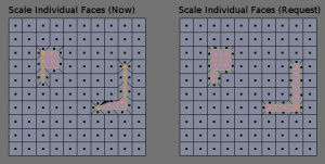
- (6) modified the face-scaling (with individual centers) to behave more 'sane' ... it often just messes up the realations of the faces and
- (7) edge-scaling to their individual centers.
I'm speaking Blender 2.42a here, as i imagine this feature request is a bit old already.
--Hoehrer 11:33, 25 September 2006 (CEST)
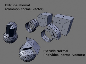
Added example images: Mind you that the 'Normal Extrude' examples are symetrical ones that can be already made by region-extrude & scale-by-center-of-geoemtry using the cursor. I've just choosen them to quickly show how the extrude should behave, But the extrude-along-individual-normals should work no matter what geometry is used ... e.g. it should also work on Elizabeth.
--Hoehrer 16:08, 25 September 2006 (CEST)
Additional note: This face-scaling behaviour is quite similar to the 'inset' suggestion below, but can be used in more situations.
--Hoehrer 14:26, 26 September 2006 (CEST)
Concerning (3) extrude selected faces along their individual normals.: Woot, using [E]->Region->0 and AltS seems to do exactly that :D I've worked such a long time with Blender and didn't yet know this? What a waste of time ;)
It's not a perfect solution since the faces are not (always?) parallel to their original location, but it's a start. Compare the cube in the image with the one created with alt+s. This also means you can't do e.g "[E]->Region", AltS and AltS again into the same direction.
--Hoehrer 11:51, 29 September 2006 (CEST)
Inset option
It will be very useful (tm) to have a inset option for face editing like other programs like Wings3D, among other characteristics of this program like extrude/displace ... in the normal direction (already requested in the first suggestion of this page), and a mirror positioning based on a face selection (I had problems sometimes placing the halfobject with the options of the current mirror modifier).
scaling of multiple faces
I see that they all scale along a common central point thats most of the time not usefull. If i select groups of faces on a mesh that arent conected i want them to scale to theire local centerpoint so they stay in theire position. Now you have to move them all manualy after a scaling operation , that sucks.
A "scale faces individual centers" is now available in face-select mode (see center-dropdown) Blender 2.42a--Hoehrer 12:04, 25 September 2006 (CEST)
duplicating an object when moving with the grab function by keeping shift pressed.
If while moving (g key)shift key is pressed the original stays in its place and a copy of the object is moved , seen in max, and a great timesaver.
-- Blenderwiki.ysvry - 04 Apr 2005
How is that any more helpful than the current Shift/Alt+D object duplicate/linked copy? Those automatically put you in grap mode. -- [[TedSchundler#29Apr105 TS]] well its a one key press instead of 3. :) -- Test.ysvry#21Jul105
Pinning vertices in edit mode.
I'm currently working on character model, and where the neck connects to the body, I have sepparated them. I have two meshes, and the vertices at the bottom of the neck match up with the start of the neck on the torso. However, as I am using proportional edit, the vertices at the top of the torso have become unaligned. That's not a problem unless they get mixed up and it makes it hard to sort them out in the end. This isn't the best example, but I know there have been times when I wanted some vertices to stay put, especially using propotional edit.
-- MattHoecker - 25 Apr 2005
I think hiding the verticies may work for you. Also, in CVS (soon to be 2.37), PET can work in connected-geometry (topology aware) mode. Doing PET in that mode uses the distance along the surface of connected verts. So it won't affect unconnected surfaces, or back sides of the same surface. -- [[TedSchundler#29Apr105 TS]]
Arbitrary Rotation Axis
I would like to be able to rotate a group of vertices/edges/faces about an arbitrary axis specified by a pair of vertices or an edge. As far as I can tell, this isn't currently possible. This ability can be approximated by placing the 3D cursor at the midpoint of the edge and then rotating the vertices around the cursor in different planes. However, this method is inaccurate in practice.
Clipping volumes
Allow clipping volumes to be placed arbitrarily in the 3d view. Any vertices that are not in the clipping volume do not get shown. This would allow the user to really focus in on the current work area, without the clutter of univolved geometry confusing the view and complicating vertex/edge/face selection.
This would also allow the user to see (and edit) inside meshes while in a solid draw mode, and inspect the interior with visual feedback simply not available in wireframe mode.
Layers can be used to help clean up the work view, but they are unwieldy and limited compared to this solution, especially since you can't put different vertices within the same mesh on different layers. (at least that I'm aware of)
In particular, I would be interested in two different types of clipping volumes, both of which are just boxes. a) a box placed like a normal object in world coordinates.
b) a box which stays relative to the camera. By camera, I mean the actual opengl one which shows the 3d view, not a blender camera that you place in the scene.
Visible vertices which have edges that pass outside the clipping volume may be indicated with a different color. Several volumes maybe could be placed, and the user chooses which one is active.
-- JonathanRichardson - 29 Jul 2005
Visible edges in object mode
I would like an option to allow edges *which are not part of faces* to be visble in object mode, and allow the lines to be colored according to vertex color. Sometimes I use blender in a sort of Cad-like way, and I want to draw with lines as opposed to faces. I'd like the lines to stay visible.
Maybe have an option to select line width.
-- JonathanRichardson - 29 Jul 2005
DoubleClick to put a vertex on a line & more:
This would be very useful for me at least:when the mouse hoovers near an edge make it change colour in editmode to let the user know he could operate on it and with doubleclick a vertex is added in the place of the click(i mean anywhere on the segment-doing this with subdivisions is quite annoying.
Another good thing would be to be able to delete a vertex(es) that stand(s) on a straight line without loosing the whole line.
Something that i would appreciate enormously is being able 1) to subdivide on X,Y,Z separately like in other apps and 2) probably making different tipes of subdivision (on a face for example:from centre,only rows,only columns,circular-web like,etc).This last i don't know if it's very needed but i'd like it.
As far as i know you can't change the view of the camera from within the camera view(NUMPAD0).So yu've got to place it manually and then press 0 on the numpad to see if it's ok,then nedd again to pass through the 1,3,7 numpads to set it right.Much time.Sorry if i'm wrong and wasting space here. 10x
-- FordFlorin - 03 Aug 2005
- %ATTACHURL%/ExtendedSnap-Menu.pdf ExtendedSnap-Menu.pdf: Blender workflow could be faster and more intuitive, especially if accuracy is important!
Mesh & Object Modifier
Nodal Interface
Create parametric nodal modeling interface. Implement parametric mesh, curve, surface, armature creation nodes. Add selection nodes which create vertex, edge/curve, polygon/surface, object groups. Selection could be done on a on an interactive or patterned basis which would return index numbers for selection. Connect modifiers in a branching tree structure, not just a stack. Bartrobinson 14:34, 5 February 2009 (UTC)
Add Rotation to Array Modifier
Allow specification of an axis or an object, angle, and number in array. Bartrobinson 14:34, 5 February 2009 (UTC)
Shell modifier
It will be very useful to have a "shell modifier" like other programs like 3dmax, to add thickness to the mesh surfaces. Ideasman made recently a script that do that, but it would be nice, that it works only in the selected faces too, and as a modifier not a script. (See Solidify Mesh in: Ideasman webpage)
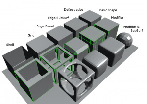
Edge-SubSurf, Edge-Bevel, Grid and Shell Modifier
I agree wholeheartly with the 'Shell Modifier' request above and (as I mentioned elsewhere in the wiki already) I propose even more cool modifiers to be added to Blender:
This image show only the basic functionality of what the modifiers should do ... imagine that each of them have at least an 'offset' and a 'divisions' value as well, so you don't need an extra "SubSurf" modifier afterwards which adds additional unneeded geoemtry to the big flat faces.
Looking at the recent development in the modifier stack I think this sort of modifiers will be do-able quite soo.
--Hoehrer 15:16, 22 September 2006 (CEST)
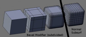
Here's an example of what I mean with the parameters for the modifers ... this example is taken nearly 1:1 (except that it starts with a sharp edge in the beginning) from the options of the current bevel function. Some options to thell the modifier 'which' edges to bevel would be great too (e.g when two faces are in a 0-degree angle a bevel is not really needed).
--Hoehrer 15:34, 22 September 2006 (CEST)
Screw & Spin Modifier (rotation loft)
Based on the Current Spin and Screw Tools there should be a modifier too. Essential would be the possibility to use also Curves as baseobject to get real smooth and crisp shapes.
--M jack, 23 December 2006
A screw modifier that works like the "Screw" command (see [1] for examples).
--Hoehrer 13:46, 5 October 2006 (CEST)
Bend/Taper Modifier
3DS MAX has a few modifiers that allows for bending, twisting, and tapering a mesh. This is very useful for making simple characters that act highly organic. There may be work-arounds that I do not know about, but a small modifier would be nice. --i80and 20:46, 6 November 2006 (CET)
Define Shear axis
This is no big deal, but it would certainly would be handy if you could select the axis along which the Shear function works (i.e. press X->the current way, no change on start, but used to switch back to X; Y->vertical shear)
Additional a 3D-shear (global X,Y and Z) would be cool so you don't have to have the camera aligned in order to shear.
Just thinkin' :) --Hoehrer 08:38, 15 December 2006 (CET)
Better bevelObject
When using a bevelObject with a curve set to 3D I sometimes get weired twists and wrinkels.
In addition it would be great if some more functionality could be added here too:
1. For example closing the start- and/or end- holes of a resulting pipe, forming caps controled by the bevel/width/extrude options.
2. Also there could be an option to optimize the result, avoiding overlapping at sharp edges of wide pipes.
Here is the .blend: blendfile
--M jack, 23 December 2006
Nurbs- and -Surface-Curve Conversion
It should be possible to convert 3D Curves to Nurbs-Surface-Curves for skinning. Also reverse. --M jack, 23 December 2006
Proportional edit type: Follow
It' s hard to explain what I mean, but I'll try: Imagine a spring-like geometry. Now if one wants to modify one 'slice' of the spring-coil in a certain way it'll also modify all geometry of the next/previous slice that falls inside the falloff-radius ("Connected" does _not_ help here).
My proposal is to add a proportional-edit type that calculates its radius from geometry (i.e. face/edge/vertex distances) .. kinda like softbodies or IK-armatures work ... just not :)
From that analogy I also formed the "Follow" name for this type ... "follow the geometry for distance-calculation" is a bit verbose ;)
If that explanation is not good enough I could try to produce an image of what I mean. Just contact me :)
--Hoehrer 17:30, 14 April 2007 (CEST)
Spline Tools Integration In UV/Image Editor For Masking
This can already be done via an ortho camera and a background image but the camera out put must be the same size as the image input. This render has to be reimported or placed a separate scene. Allow the mask to be used as an image or texture node (preferably as a procedural since the splines are already vector), separate from the image being masked, for reusability. Allowing keyframing of the mask would further enhance it's usefulness.--RamboBaby 08:51, 21 May 2007 (CEST)
DupliVerts as a Modifier
Although DupliVerts is a powerful tool, it lacks some more control that would be desired sometimes. Now, you can only affect all objects that are duplicated in the same way, so the result is always the the same object.
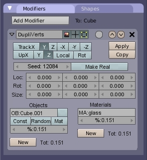
I would like to propose the recreation of Dupliverts as a modifier. This might help to move it from Anim Setting tab to the modifier stack, which I think is a better place for Dupliverts, used mainly as modeling tool. But them main improvement would be adding more control and variation to the result.
Firstly, the basic function should remain the same. The "Track" and "Up" buttons should be copied, and if only one object will be dupliciated, it will work like Dupliverts we know now.
Secondly, the user will be able to duplicate multiple objects. The total number of duplicates will be based on number of vertices the parent object has. The number of objects should not be limited, so they will be listed in a list (the "Objects" row). The distribution of them will be random, user only specifies the propability (or percentage) that the object will appear. For each object, location, rotation and size variantion could be defined and also the Tracking and Up axis. Either constant ("Const" button) or random ("Random! button) offset might be possible. This is per object setting, so it could be possible to have one type of object uniformly rotated and another randomly. This might be set in the 3x3 matrix for location, rotation and size on each axis separately. The small blank button is selector, because it might be hard to orientate when more objects were added and for each a big part of the tab be created.
Thirdly, the modifier should enable mixing duplicated objects with different materials. The number of objects should be independant. It is possible to try to duplicate object with multimaterial assigned, so an option to preserve assigned material for object moght be handy (the "Mat" button).
The "Seed" field is for distribution and random transformations. The "Make Real" button will determine the result of modifier. After applying this modifier, the user might get diffrent results. If "Make Real" was not pressed, it will generate a new single mesh with correctly assigned materials and vertex groups based on duplicated objects. If the "Make Real" was pressed, then the result should be separate objects, each with correct material and local transformations (in contrast what the result after making duplis real is now, each object having the same local trnaformation only the mesh transformed).
Possible problems: If the "Rot" button is pressed, the duplicates are alligned with vertex normals, so the duplicates might be transformed only on global axes, or more preferably on they respective local axes. For this, it might be good to create vertex groups based on the names of objects, and for each also remember local transformations. Current limit for multimaterials is 16, which might be very limiting for this modifier.
Eventually, the entire modifier could be Dupli modifier, and you can choose between DupliVerts, DupliFaces and DupliGroups.
Look at this thread on BlenderArtists
--MynPheos 17:35, 2 June 2007 (CEST)
Text Editor
- Word wrapping for the text editor, useful for documentation and such (Scrolling would be limited to the Y axis then)
View Frustum Culling Modifier
Similar to the Decimation modifier in that it removes polygons, except it culls faces outside the view frustum of the camera. I guess this would allow polygon-heavy models to get lighter the closer you get to them when they are in view. Ideally this would allow a variable amount of a buffer area around the view frustum, for example to keep all the polygons inside the frustum plus polygons up to 1 meter outside the frustum.
Perhaps there is a technical reason why this doesn't makes sense? I am thinking about a model which perhaps starts off at medium complexity, but then has a SubSurf modifier added to it, taking it up to a higher complexity and polygon count. Then to get it back under control because the camera will only see smaller portions at a time, you could add the View Frustum Culling Modifier to only keep the polygons you need. But if the subsurf modifier allocates all the memory for the high polygon model, then the VFC Modifier cuts some out, but has to allocatte more memory anyway, it'd be a waste perhaps.
Summit sides bribes
An excellent feature is missing in Blender and to create between the sides of selected cross or are tangent at a summit auto, good for use with the best snap or work easily imports QCad where there are many in edit mode sides that meet but do not have a summit that will also join ... first or later it happens to all that it wants a summit meeting between the sides that touch, each artist can happen.
http://img25.imageshack.us/i/tangep.jpg/
italiano:Un'ottima funzione mancante in Blender e quella di creare tra dei lati selezionati che si incrociano o che sono tangenti un vertice in automatico ,ottimo per utilizzare al meglio gli snap o per facilmente lavorare le importazioni di Qcad dove vi si trovano in edit mode molti lati che si incrociano ma non hanno un vertice che li uniscano ...inoltre primo o poi a tutti capita di volere un vertice tra lati che si toccano ,ad ogni artista può capitare .
Precision instrument
Pech avoid having the most accurate 3D control of the composition with each line calculated mm, cm etc ... is not only a prerogative of each and there is no need to create a department cad but just a panel, including a script "maybe! "But that takes account of the entire process of composition so determined! In reality it would be a better tool with real time conversion of the blend measure in millimeters, centimeters, etc. ...
work hours as the window panel or script or tool?
First, you could position the cursor and then you create the first summit (. P) taking this position in the panel compared the "xyz" with "lines of command XYZ" for the summit itself which is important to coordinate with the position of vertices that follow, now from the top should start a line (or a 'ellipses) and for giving the direction the best thing is to tap the measurement of the degree and then you choose the direction of the line between, or "360 degrees XY" (A) around at the top with a 'special' line of command, "decided the direction you can draw the line! Now the line is considered many things, mainly it is known that ends with a height that coincides with "Z" with respect to the ground floor and then a "line of command to the height" (. C): it takes! then we know that the second point on the line that is formed has a distance from the point first and then a "line of command to the distance" (. D), considering to follow the line of earth and then the axis' Z "you can calculate the degrees of 'height and then put a" line of command for grades Z,
course, each "line of command" adapts to the other for absolute precision, now we need a way to create a circle or an ellipse and a line-up that can be "radius or line of a circle or maximum height for an ellipse is to first create a "line of command to the height ellipses (. F) then calculates the position on line or by percentage or by precise measurements on the line with a 'special' line of command "and a" line of command for grades median "(J) to create more side ellipse, or a 'different way to create ellipses
and to consider the search for the point and then as you create the second point with the calculation of height and so ... !
If you wanted to create an instrument you would be able to have the 'preview of the line and' ellipse entitled to move with the mouse, can also use the snap while numbers are formed in the various lines of command! would have a T shape with a knob for each more extreme, the central joining point of the preview to that of straight
http://img89.imageshack.us/i/tecnoblender.jpg/
italiano:
Pechè evitare di avere il più accurato controllo della composizione 3D con ogni linea calcolata a millimetro ,cm ecc... non è solo una prerogativa di cad e non c'è la necessita di creare un reparto cad ma basta un pannello ,anche uno script “forse! “ma che tiene conto di tutto il processo di composizione in modo calcolato ! In realtà sarebbe meglio uno strumento vero e proprio con tanto di conversione dalla misura blend in millimetri,centimetri ecc...
ora come lavorerebbe tale pannello o script oppure strumento ?
Per prima cosa si potrebbe posizionare il cursore e da li si crea il primo vertice (.P)tenendo presente nel pannello la posizione rispetto “x y z” con dei “righi di comando XYZ” del vertice stesso che è importante per coordinarsi con la posizione dei vertici che seguono ,ora dal vertice dovrebbe partire una retta (o un' ellissi) e per dare la direzione la migliore cosa è sfruttare la misurazione del grado e quindi si sceglie la direzione della linea tra o “360 gradi X Y”(A) attorno al vertice con un' apposito “rigo di comando ”,deciso la direzione si può tracciare la retta! Ora della retta si considerano molte cose ,principalmente si sa che termina con un'altezza che coincide con “Z” rispetto al piano terra e quindi un “rigo di comando per l'altezza ” (.C): ci vuole ! poi si sa che il secondo punto della retta che si forma ha una distanza dal primo punto e quindi un “rigo di comando per la distanza “(.D), a seguire considerando la linea di terra e quindi l'asse “ Z” si può calcolare i gradi del' altezza e quindi metterei anche un “rigo di comando per i gradi Z” ,
naturalmente ogni “rigo di comando” si adatta agli altri per avere un'assoluta precisione ,ora c'è bisogno di un modo per creare un cerchio o un'ellissi e dato che una retta può essere “raggio o linea mediana di un cerchio o altezza massima per un'ellissi” si crea per prima cosa un “rigo di comando per l'altezza ellissi “(.F) poi si calcola la posizione sulla retta o con percentuali oppure con misure precise sulla retta con un' apposito “rigo di comando ” e inoltre un “rigo di comando per i gradi mediani ”(J) per creare ellissi più laterali ,oppure un' altro modo per creare ellissi
e quello di considerare la ricerca del punto e quindi come si è creato il secondo punto con tutti i calcolo d'altezza ecc... !
Se si volesse creare uno strumento si avrebbe la possibilità di avere l' anteprima della retta e dell' ellissi potendolo spostare con il mouse ,potendo usare anche gli snap mentre si formano numeri nei vari righi di comando !! avrebbe una forma a T con un pomello per ogni estremo più quello centrale che congiunge l'anteprima dell'ellissi al quella della retta
2D Image Conversion To 3D
- It would be possible and AWESOME of someone could write code to take a greyscale 2D Image and automatically "convert" it as an engraving into a 3D object. This could be accomplished by having the user select whether black or white means deep, entering a % maximum relief depth (% of the 2D picture dimensions IE at 50%, pitch black would 'relief' back by 50% of the picture size), and entering a % shade sensitivity threshold. The code would take these variables and draw the 3D mesh, connecting all the verticies to form faces/edges. This would be very very cool.
3D Charts and Graphs with Animation
- Believe it or not, there is some significant demand for this. I'd recommend just going through Open Office's charts and building a module in Blender to make the charts (and let you change values in them over an animation).
poly spline type mesh interpolating option
- in some programs like art of illusion i have seen this implemented it
is like a combo of a nurbs surface and a mesh
and it maybe worth investigation.
