利用者:Kesten/Projects/CurvesWiki Proposal
Curves
To create a curve, go to Add Curve and select from the options. In Object Mode with the curve selected you can Scale s , Move ("Grab) g or rotate r the entire curve. To edit a curve, switch to Edit Mode and click the Curves menu option.
Curves and Surfaces are objects just as meshes are objects except they are expressed in terms of mathematical functions, rather than as a series of points.
<push to Referenece> Blender implements both Bézier curves and Non-Uniform Rational B-Splines (NURBS) curves and surfaces. Both are defined in terms of a set of “control vertices” (or “control points”) which define a “control polygon”, though each follow a different set of mathematical laws. The way the curve and the surface are interpolated might seem similar, at first glance, to Catmull-Clark subdivision surfaces. The curve is interpolated while the surface is attracted. TDOD find wiki or other references to explain interpolated vs attracted.
Compared to Polygonal Mesh
TODO add picture of polygonal mesh One main advantage to curves over polygonal meshes is that curves are defined by less data, so can produce excellent results using less memory and storage space at modeling time. However, this procedural approach to surfaces can increase demands at render time.
</push to Reference>
Some modeling techniques like extruding a profile along a path are only possible using curves. At the same time, vertex-level control is more difficult when using curves.
<push to Reference> There are times when curves and surfaces are more advantageous than meshes, and times when meshes are more useful. It is recommended you read the section on mesh editing, which should help you decide whether to use meshes or curves in your project.
When you have finished reading and learning about Bézier and NURBS curves there are several more advanced examples on the application of curves in the tutorials section for modeling complex objects. </push to Reference>
<update to 2.6>
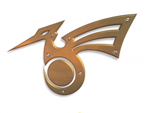
There is a Working example that shows how to create an interesting bird-like logo. The tutorial covers most aspects of working with Bézier curves including: adding curves, setting up a background image as a template guide and beveling the final curve.
In addition, the Tutorial section has examples on both Skinning and Curve deform techniques.
</update to 2.6>
Finding Curve Tools
You can browse by menu options by selecting Curves in Edit Mode. You can learn about the python calls by lowering the Info Window and by opening a python console and typing bpy.ops.curve followed by {{Literal|Ctrl Spacebar}
The Select menu is customized to curves if the curve is selected in Edit mode of the 3D view. Further options can be found in the Specials menu (W).
Visualization
In Edit mode, the curve is drawn as a black line, and in Solid shading (or Shaded, …), the closed curves are filled with a flat surface. 3D curves have additional “arrows” all along the curve, illustrating both the direction and the relative speed of the movement objects will have when following them as path (unless a custom Speed Ipo is defined…).
<verify for windows and mac>
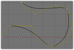
Each control point is drawn in orange. Bézier “vectors” are materialized with salmon-pink lines, whereas NURBS vertices are linked by yellow lines. As with meshes, selected vertices are highlighted in yellow (with a lighter shade for the active element).
Control Points and Segments
Curves are mainly defined by their control points, as described below in their respective section. However, you will sometimes encounter another concept, the “segment” of curve. A segment is defined implicitly by its two adjacent control-points. Unlike with meshes, you can’t explicitly select a segment – you must select its two adjacent control-points.
Adding Points
Extrude
You can add new points by clicking Curves . This only works if you have selected the first or last points on the curve.
Subdivide
You can add points to the middle of a curve by selecting two consecutive points followed by Curves . After this operation, the entire segment made of the three points is selected. You must select only the newly created point to move it independently.
Multiple Curves
If you have more than one curve in the 3D View, you may need to switch to Object Mode and select the other curve, the switch back to Edit Mode, if you wish to change which curve is being edited. You may join curves of the same type in Object Mode with J and separate them in Edit Mode with P. If you separate two objects, you may need to reset the origin (axes for the object) by selecting in Object Mode, Object -> Origin to Object.
Closed Curves
Curves may be closed and opened in Edit Mode by pressing the Curve -> Toggle Cyclic, or pressing Alt C
Nurbs
Curve Structure
About U and V coordinates
U and V are the conventional names of parametric “coordinates” components (note that these are the same names as texture ones…). They are used to define the resolution, the “knots” for NURBS, etc., along given “axis”. For curves, only the U component is relevant (as they have only one dimension, they are lines). The V component is used by NURBS surfaces.
|
Hiding Elements
As in Object mode, you can hide what is selected, and then reveal what was hidden. This is very handy to clean up a bit your views, when you are working on a complex model with thousands of vertices…
To hide, use CtrlAltH, the Hide button of the Curve Tools1 panel, or use the Curve » Show/Hide Control Points » Hide Selected menu option.
To reveal what was hidden, use AltH, the Reveal button of the Curve Tools1 panel, or the relevant option in the same Curve » Show/Hide Control Points menu.
<TODO: Add sections for other menu subitems like segment and control points>
<update to 2.6 | "I don't know the equivalent in 2.6">
Curve Resolution
Although these curves are continuous mathematical objects, they must nevertheless be represented in discrete form (set of small segments) from a rendering point of view. This is done by setting a resolution property, which defines the number of points which are computed between every pair of control points. Note that this applies only to Bézier curves, and is different for NURBS.
You have in fact three resolution settings, two in the Curve and Surface panel, and one in the Curve Tools panel:
- DefResolU: The resolution applied by default to all curves of the object, both in the 3D views and at render time.
- RenResolU: The resolution applied by default to all curves of the object when rendering, if not set to zero (else DefResolU is used).
- Resol U: This setting is only available in Edit mode, it will modify the resolution of the curves (partly) selected currently. Note that it is reset to the DefResolU value each time you modify this setting.
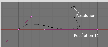
A separate resolution can be set for each curve by adjusting the DefResolU field of the Curve and Surface panel. The default is 6. (Bézier resolution example) is an example of the same curve, superimposed with the aid of Gimp, showing two different resolution settings. The lighter shaded curve has a low resolution of 4; the curve begins to look linear. The darker curve has a resolution of 12 and is very smooth. Note that high resolutions may look nicer but they can slow down interactive rendering if there is a large number of curves (and/or if these ones have a large amount of control points).
</update to 2.6>
2D and 3D Curves
By default, (except for the Path primitive), new curves are 2-dimensional, meaning all control points lie in the same plane (X-Y in Local space). This allows automatic filling of closed curves.
<TODO: delete this. no longer relevant. Or replace with section on how to restrict to 2D>
However, you might want to be able to place your control points freely in 3D space. To do so, enable the 3D button of the Object Data panel. Note that you will lose the closed curves filling, and arrows will be displayed as per the Visualization section above.
Closed and Open Curves
Curves (Bézier or NURBS) are mono-dimensional: they are lines, that never crosses themselves (i.e. control points are only linked to at most two others, forming a continuous line, without any fork…). However, curves can be open (i.e. they start and end points are not linked by a curve segment) or closed. Closed curves are solid, inasmuch that Blender adds a solid flat face inside them (unless they are made 3D).
<push to Reference>
Béziers
Bézier curves are the most commonly used curves for designing letters or logos. They are also widely used in animation, both as paths for objects to move along and as IPO curves to change the properties of objects as a function of time.
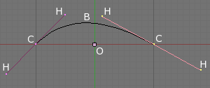
(Curve example) is the most basic Bézier curve you can create. It consists of two control points or vertices, labeled “C”, the curve “B”, handles “H” and an object center “O”.
A handle “H” defines the tangent vector to the curve in point “C” (on its side). The “steepness” of the curve is controlled by the handle’s length (“H” to a “C”). The longer a handle is the steeper the curve (i.e. the more curve wants to hug the handle).
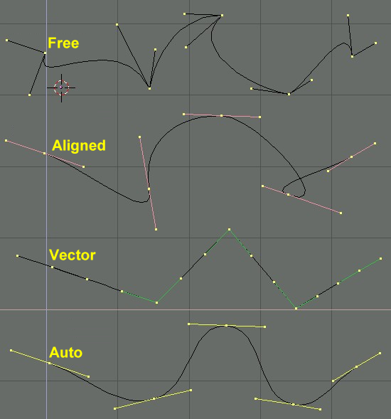
There are four types of handles (Types of Handles for Bézier curves):
- Free Handle (black). The handles are independent of each other. To convert to Free handles use H. H also toggles between Free and Aligned.
- Aligned Handle (purple). These handles always lie in a straight line, and give a continuous curve (without sharp angles…). Hotkey: H (toggles between Free and Aligned).
- Vector Handle (green). Both parts of a handle always point to the previous handle or the next handle (this allows you to create curves made of straight lines!). Hotkey: V.
- Auto Handle (yellow). This handle has a completely automatic length and direction, set by Blender to ensure the smoothest result. Hotkey: ⇧ ShiftH.
Handles can be grabbed, rotated and scaled exactly as ordinary vertices in a mesh would. As soon as the handles are moved, the handle type is modified automatically:
- Auto Handles becomes Aligned;
- Vector Handles becomes Free.
NURBS
NURBS curves are defined as rational polynomials and are more general, strictly speaking, than conventional B-Splines and Bézier curves inasmuch as they are able to exactly follow any contour. For example a Bézier circle is a polynomial approximation of a circle, and this approximation is noticeable, whereas a NURBS circle is exactly a circle. However, a NURBS cannot have real sharp angles in it, unlike a Bézier curve…
NURBS curves require a little bit more understanding of the underlying components that make up a NURBS curve in order to get full use of them. They have a large set of variables, which allow you to create mathematically pure forms. However, working with them requires a little more discussion on the various parts of a NURBS curve.
Note
NURBS are a very complicated topic, I think they might be a good subject for a “Theory” article – written by someone knowing them deeply! (For a start, here's the Wikipedia page.)
|
Knots
We start with Knots. NURBS curves have a knot vector, a row of numbers that specifies the parametric definition of the curve (i.e. they describe the range of influence for each of the control-points). Remember the control-points from Bézier curves, NURBS have them too and each control-point affects some part of the curve along that range. The control-points appear as purple vertices.
Note that knots setting concerns only open NURBS, not closed ones.
(Default Uniform curve) is the default NURBS curve created using the NURBS Curve menu item from the toolbox’s Add menu and is an example of a Uniform curve. The curve itself is drawn in black, labeled “C” and the control-points are drawn in purple; one out of the 4 is labeled “P”.
You can’t manipulate the Knot vector directly but you can configure it using three presets: Uniform, Endpoint and Bezier.
The Uniform button of the Curve Tools panel produces a uniform division for closed curves, but when used with open curves you will get “free” ends, which are difficult to locate precisely.
The Endpoint button sets the Knot vector in such a way that the first and last vertices are always part of the curve, which makes them much easier to place. (Endpoint curve) is an example of applying the Endpoint button to the (Default Uniform curve). You can see that the curve has now been pulled to the end control-points labeled “A” and “B”.
Finally, Bezier “Knot vector” (I’m not really sure this remains a real knot, in fact…) make the NURBS control points mimic the Bézier control points behavior. This works only with two orders value (see below): 3 and 4.
- With an Order of 3, all odd points act as a center of a Bézier control point, and all even points act as a Bézier handle. So vertices (1,2,3) define a first Bézier segment, (3,4,5) a second one, and so on…
- With an Order of 4, all four groups of control points define a Bézier segment, i.e. vertices (2,3,4,5) define a first segment, (5,6,7,8) a second one, etc. Note that here, the first vertice is for some reasons unused…
Order
The Order field of the Curve Tools panel is the “depth” or degree of the curve (i.e. you are specifying how much the control-points are taken into account for calculating the curve shape).
Order 1 is a point and is not an available depth setting, Order 2 is linear (Order 2 curve), Order 3 is quadratic (Order 3 curve), (Order 4 curve) is cubic, and so on. The valid range is 2 to 6. Notice that as the Order rises the curve moves away from the control-points.
If your curve has 6 or more control-points the Order can not be set higher than 6. 6 is the highest Order allowable. If you have less than 6 control-points then the highest Order is limited by the number of control-points. For example, if your curve has 5 control-points then the highest Order allowable is 5.
Always use an order of 5, if possible, for curve paths because it behaves fluidly under all circumstances, without producing irritating discontinuities in the movement. For example, if you have a cube assigned to travel along a NURBS path with an Order of say 2 then the cube will appear to move roughly (or jerky) along the path.
Math Note
Mathematically speaking the Order is the order of both the Numerator and the Denominator of the rational polynomial defining the NURBS curve.
|
Weight
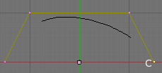
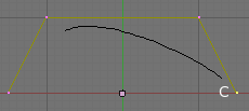
NURBS curves have a Weight (Curve Tools panel) assigned to each control-point that controls how much each “pulls” on the curve. Think of it as if each control-point has an arm that reaches out and grabs hold of the curve and tries to pull on it. The larger the Weight the more the control-point pulls on the curve, see (Weight of 5) and (Weight of 20). The valid range of Weight settings are 0.1 to 100.0.
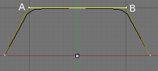
The larger Weight of 20 pulls the curve towards the control-point labeled “C”. Each control-point can have a different Weight setting. As the Weight for a control-point increases the curve will hug the control-points closer. If the Weights are large enough the curve will almost follow the control-points, see (Weight of 100).
The control-points can effectively compete with each other. For example, the control-point with the largest Weight will pull the curve towards it and away from the others. If all the control-points have the same Weight then the Weight is effectively canceled, as if none had Weights.
In (Weight of 100) the top two control-points have their Weight set at 100.0, labeled “A” and “B”. The opposite control-points have their Weight at 1.0. You can see that the curve is “pulled” toward control-points “A” and “B”. And at such a high Weight the curve almost follows the control-points.
To see the Weight value of a control-point, select it, open the Transform Properties panel using N, and look at the Vertex W field. The Weight field doesn’t show the Weight!
Preset Weights
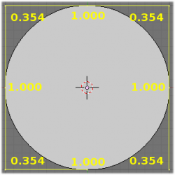
NURBS curves can create pure shapes such as circles (note that a Bézier circle is not a pure circle). To create pure circles, you must set to specific values the weights of the control-points – some of which are provided as presets in the Curve Tools panel (lower right corner). This is not intuitive, and you should read more on NURBS before trying this.
Basically, to produce a circular arc from a curve with three control-points, the end points must have a unitary weight, while the weight of the central control point must be equal to one-half the cosine of half the angle between the segments joining the points. Lets take an example: if you have three control-points creating a right angle, to get a quadrant, you would set the center point’s weight to cos(90/2)/2 = cos(45)/2 = sqrt(2)/4 = 2**-1.5 ≃ 0.354 (these settings are valid with an order of 4… so you must have at least four control points, as with three points – and hence an order of 3 –, you won’t get a “circular” quadrant!).
The other presets are more useful for NURBS surfaces (to create spheres, cylinders, …).
Primitives
Blender can add five different curve primitives, two Bézier and three NURBS:
- Bezier Curve adds an open 2D Bézier curve with two control points.
- Bezier Circle adds a closed, circle-shaped 2D Bézier curve (made of four control points).
- NURBS Curve adds an open 2D NURBS curve, with four control points, with Uniform knots.
- NURBS Circle adds a closed, circle-shaped 2D NURBS curve (made of height control points).
- Path adds a NURBS open 3D curve made of five aligned control points, and with Endpoint knots and the CurvePath setting enabled.
