Doc:2.6/Manual/Modeling/Curves/Editing/Advanced
Page status (reviewing guidelines)
Partial page Images
some screenshots are correct, but taken from the 2.4
|
Curve Deform
Curve Deform provides a simple but efficient method of defining a deformation on a mesh. By parenting a mesh object to a curve, you can deform the mesh up or down the curve by moving the mesh along, or orthogonal to, the dominant axis. This is a most useful tool to make an object follow a complex path, like e.g. a sheet of paper inside a printer, a film inside a camera, the water of a canal…
The Curve Deform works on a (global) dominant axis, X, Y, or Z. This means that when you move your mesh in the dominant direction, the mesh will traverse along the curve. Moving the mesh in an orthogonal direction will move the mesh object closer or further away from the curve. The default settings in Blender map the Y axis to the dominant axis. When you move the object beyond the curve endings the object will continue to deform based on the direction vector of the curve endings.
If the “curve path” is 3D, the Tilt value of its control points will be used (see the Extrusion section above) to twist the “curved” object around it. Unfortunately, the other Radius property is not used (it would have been possible, for example, to make it control the size of the “curved” object…).
| A Tip | |
| Try to position your object over the curve immediately after you have added it, before adding the curve deform. This gives the best control over how the deformation works. |
Use modifiers!
The Curve Deform relationship is now also a modifier, called Curve. The Curve modifier function acts the same as its counterpart, except that when the modifier is used, the “dominant axis” is set inside its properties – and the Track X/Y/Z buttons no longer have an effect on it. And you have some goodies, like the possibility, if “curving” a mesh, to only curve one of its vertex groups…
|
Interface
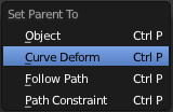
When parenting an object (mesh, curve, meta, …) to a curve (CtrlP), you will be presented with a menu (Make Parent menu).
By selecting Curve Deform, you enable the curve deform function on the mesh object.
The dominant axis setting is set on the mesh object. By default the dominant axis in Blender is Y. This can be changed by selecting one of the Track X, Y or Z buttons in the Anim Panel, (Anim settings panel), in Object context (F7).
Cyclic (or closed) curves work as expected where the object deformations traverse along the path in cycles. Note however that when you have more than one curve in the “parent” object, its “children” will only follow the first one.
The Stretch curve option allows you to let the mesh object stretch, or squeeze, over the entire curve. This option is in Editing Context (F9), for the “parent” curve. See (Curve and Surface panel).
Example
Let’s make a simple example:
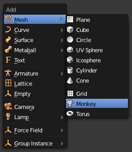
- Remove default cube object from scene and add a Monkey (⇧ ShiftA » Add » Mesh » Monkey, Add a Monkey!)!
- Press ⇆ Tab to exit Edit mode.
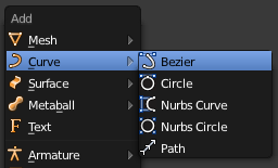
- Now add a curve (⇧ ShiftA » Add » Curve » Bezier Curve, Add a Curve).
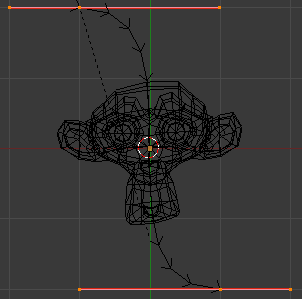
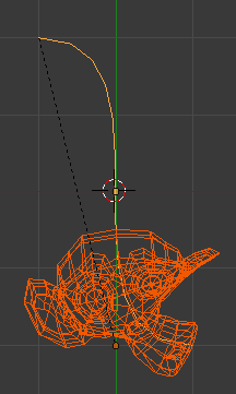
- While in Edit mode, move the control points of the curve as shown in (Edit Curve), then exit Edit mode (⇆ Tab).
- Now, you can use the new, modern, modifier way of “curving” the Monkey:
- Or you can choose the old, deprecated method (note that it creates a “virtual” modifier…):
- The Monkey should be positioned on the curve, as in (Monkey on a Curve).
- Now if you select the Monkey (RMB
 ), and move it (G), in the Y-direction (the dominant axis by default), the monkey will deform nicely along the curve.
| A Tip | |
| If you press MMB |
- In (Monkey deformations), you can see the Monkey at different positions along the curve. To get a cleaner view over the deformation I have activated SubSurf with Subdiv to 2, and Set Smooth on the Monkey mesh (F9 to get Editing context).
| A Tip | |
| Moving the Monkey in directions other than the dominant axis will create some odd deformations. Sometimes this is what you want to achieve, so you’ll need to experiment and try it out! |
Curve Extrusion
This section covers methods for extruding curves, or giving them thickness, and how to control the thickness along the path.
Extrusion
Mode: Object or Edit mode
Panel: Curve and Surface (Editing context, F9)
Ah! The extrusion! Probably the most interesting tool of the curves for modeling, especially with the bevel/taper/Tilt/Radius options… Note that this has nothing to do with the Extrude (E) command, described in the previous page!
We will see the different settings, depending on their scope of action:
- Width
- This controls the position of the extruded “border” of the curve, relative to the curve itself. With closed 2D curves (see below), it is quite simple to understand – with a Width greater than 1.0, the extruded volume is wider, with a Width of 1.0, the border tightly follows the curve, and with a Width lower than 1.0, the volume is narrower… The same principle remains for open 2D and 3D curves, but the way the “outside” and “inside” of the curve is determined seems a bit odd…
- It has the same effect with extruded “bevel” objects…
- Tilt
- This setting – unfortunately, you can never see its value anywhere in Blender – controls the “twisting angle” around the curve for each point – so it is only relevant with 3D curves!
- You set it using the Tilt transform tool (T, or Curve » Transform » Tilt), and you can reset it to its default value (i.e. perpendicular to the original curve plane) with AltT (or Curve » Control Points » Clear Tilt).
- With NURBS, the tilt is always smoothly interpolated. However, with Bézier, you can choose the interpolation algorithm to use in the Tilt Interpolation drop-down list of the Curve Tools panel (you will find the classical Linear, Cardinal, B Spline and Ease options…).
Simple Extrusion
Let’s first see the “simple” extrusion of curves, without additional bevel/taper objects.
- Extrude
- This controls the width (or height) of the extrusion. The real size is of course dependent on the scale of the underlying object, but with a scale of one, an Extrusion of 1.0 will extrude the curve one BU in both directions, along the axis perpendicular to the curve’s plane (see below for specifics of 3D curves…).
- If set to 0.0, there is no “simple” extrusion!
- Bevel Depth
- This will add a bevel to the extrusion. See below for its effects…
- Note that the bevel makes the extrusion wider and higher.
- If set to 0.0, there is no bevel (max value: 2.0).
- Bev Resol
- Controls the resolution of the bevel created by a Bevel Depth higher than zero.
- If set the 0 (the default), the bevel is a simple “flat” surface.
- Higher values will smooth, round off the bevel, similar to the resolution settings of the curve itself…
We have three sub-classes of results, depending on whether the curve is open or closed or 3D:
- Open 2D Curve
- The extrusion will create a “wall” or “ribbon” following the curve shape. If using a Bevel Depth, the wall becomes a sort of slide or gutter. Note the direction of this bevel is sometimes strange and unpredictable, often the reverse of what you would get with the same curve closed… You can inverse this direction by switching the direction of the curve.
- This allows you, e.g., to quickly simulate a marble rolling down a complex slide, by combining an extruded beveled curve, and a sphere with a Follow Path constraint set against this curve…
- Closed 2D Curve
- This is probably the most useful situation, as it will quickly create a volume, with (by default) two flat and parallel surfaces filling the two sides of the extruded “wall”. You can remove one or both of these faces by disabling the Back and/or Front toggle buttons next to the 3D one.
- The optional bevel will always be “right-oriented” here, allowing you to smooth out the “edges” of the volume.
- 3D Curve
- Here the fact that the curve is closed or not has no importance – you will never get a volume with an extruded 3D curve, only a wall or ribbon, like with open 2D curves.
- However, there is one more feature with 3D curves: the Tilt of the control points (see above). It will make the ribbon twist around the curve … to create a Möbius strip, for example!
Advanced Extrusion
These extrusions use one or two additional curve objects, to create very complex organic shapes.
To enable this type of extrusion, you have to type a valid curve object name in the BevOb field of the curve you are going to use as the “spinal column” of your extrusion. The “bevel” curve will control the cross section of the extruded object. Whether the BevOb curve is 2D or 3D has no importance, but if it is closed, it will create a “tube-like” extrusion; otherwise you will get a sort of gutter or slide object…
The object is extruded along the whole length of all internal curves. By default, the width of the extrusion is constant, but you have two ways to control it, the Radius property of control points, and the “taper” object.
The Radius of the points is set using the Shrink/Fatten Radius transform tool (AltS, or Curve » Transform » Shrink/Fatten Radius), or with the Set Radius entry in the Specials menu (W). Here again, you unfortunately cannot visualize anywhere the Radius of a given control point…
The Radius allows you to directly control the width of the extrusion along the “spinal” curve. As for Tilt (see above), you can choose the interpolation algorithm used for Bézier curves, in the Radius Interpolation drop-down list of the Curve Tools panel.
But you have another, more precise option: the “taper” object. As for the “bevel” one, you set its name in the TaperOb field of the main curve – it must be an open curve. The taper curve is evaluated along the local X axis, using the local Y axis for width control. Note also that:
- The taper is applied independently to all curves of the extruded object.
- Only the first curve in a TaperOb is evaluated, even if you have several separated segments.
- The scaling starts at the first control-point on the left and moves along the curve to the last control-point on the right.
- Negative scaling, (negative local Y on the taper curve) is possible as well. However, rendering artifacts may appear.
- It scales the width of normal extrusions based on evaluating the taper curve, which means sharp corners on the taper curve will not be easily visible. You’ll have to heavily level up the resolution (DefResolU) of the base curve.
- With closed curves, the taper curve in TaperOb acts along the whole curve (perimeter of the object), not just the length of the object, and varies the extrusion depth. In these cases, you want the relative height of the TaperOb Taper curve at both ends to be the same, so that the cyclic point (the place where the endpoint of the curve connects to the beginning) is a smooth transition.
Last but not least, with 3D “spinal” curves, the Tilt of the control points can control the twisting of the extruded “bevel” along the curve!
Examples
TODO: add some “simple” extrusion examples.
TODO: add some “bevel” extrusion with Radius examples.
Let’s taper a simple curve circle extruded object using a taper curve. Add a curve, then exit Edit
mode. Add another one (a closed one, like a circle); call it “BevelCurve”, and enter its name in the BevOb field of the first curve (Editing context F9, Curve and Surface panel). We now have a pipe. Add a third curve while in Object mode and call it “TaperCurve”. Adjust the left control-point by raising it up about 5 units.
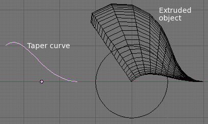
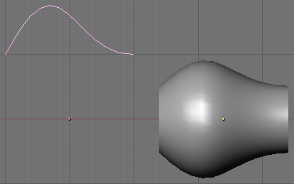
Now return to the Editing context, and edit the first curve’s TaperOb field in Curve and Surface panel to reference the new taper curve which we called “TaperCurve”. When you hit enter the taper curve is applied immediately, with the results shown in (Taper extruded curve).
You can see the taper curve being applied to the extruded object. Notice how the pipe’s volume shrinks to nothing as the taper curve goes from left to right. If the taper curve went below the local Y axis the pipe’s inside would become the outside, which would lead to rendering artifacts. Of course as an artist that may be what you are looking for!
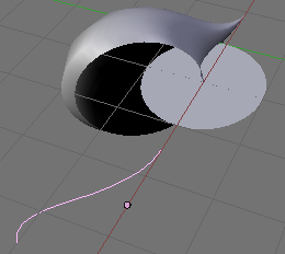
In (Taper example 1) you can clearly see the effect the left taper curve has on the right curve object. Here the left taper curve is closer to the object center and that results in a smaller curve object to the right.
In (Taper example 2) a control point in the taper curve to the left is moved away from the center and that gives a wider result to the curve object on the right.
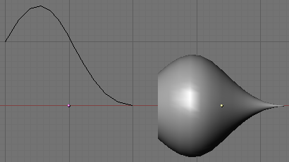
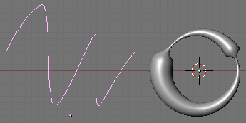
In (Taper example 3), we see the use of a more irregular taper curve applied to a curve circle.
TODO: add some “bevel” extrusion with Tilt examples.
